
"No Loop" Mode & Multi-Step Sequences
Learning Objective
Build your first working rule using No Loop mode, and learn how Steps let a single rule control several outputs one after the other.
Theory: One Shot, Then Stop
Last week you met all four Loop Modes. This week we zoom right in on the simplest one: No Loop.
A No Loop rule is a one-shot. It runs its steps from first to last exactly once, and then it is finished. It does not repeat, it does not watch a sensor, and it does not wait around. This makes it the perfect mode for learning, because you can see the whole rule happen from beginning to end and then the board goes quiet again.
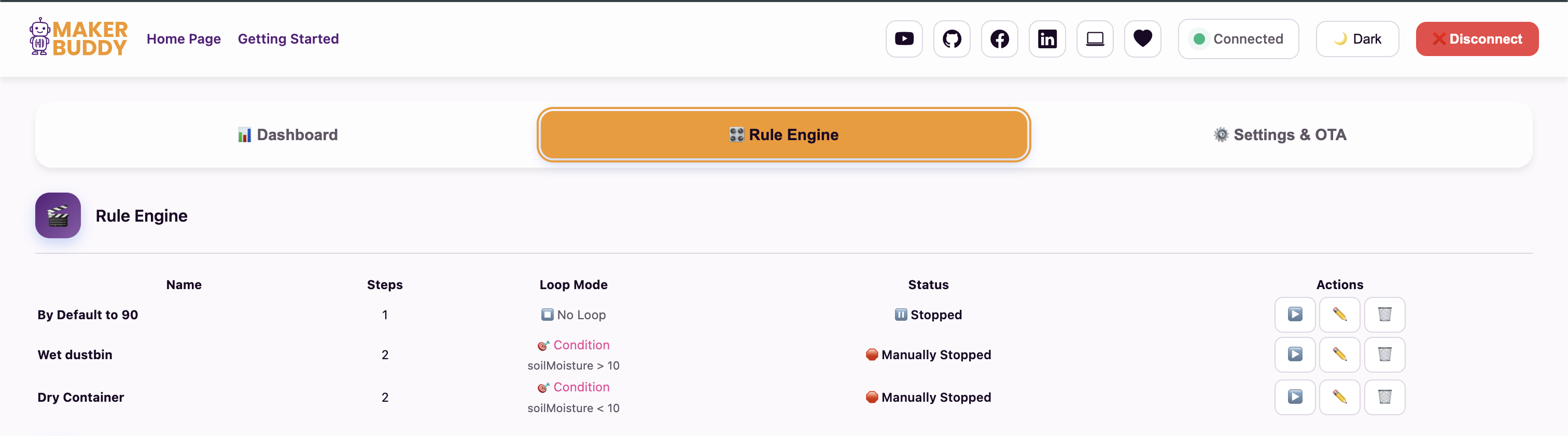
Select No Loop when the steps should run once and then stop.
When Does a No Loop Rule Actually Run?
There are three moments a one-shot rule fires:
A new enabled rule with steps runs immediately, the moment you press Save Rule.
Each saved rule card has a Start button. Press it and the one-shot fires again.
If the rule is enabled and marked to run at startup, it fires once every time the MakerBuddy powers on.
Steps: What Should the MakerBuddy Actually Do?
The Loop Mode decides when the rule runs. Steps decide what happens when it does.
Think of Steps like a shopping list. Instead of buying just one thing, you write down many things in order, and work through the list from top to bottom. In the same way, a single rule can do up to 10 things in sequence.
Adding Steps to a Rule
When you create a rule, you will see a Steps panel near the bottom of the form. Click "+ Add Step" to add another one. Each new step runs right after the previous one finishes.
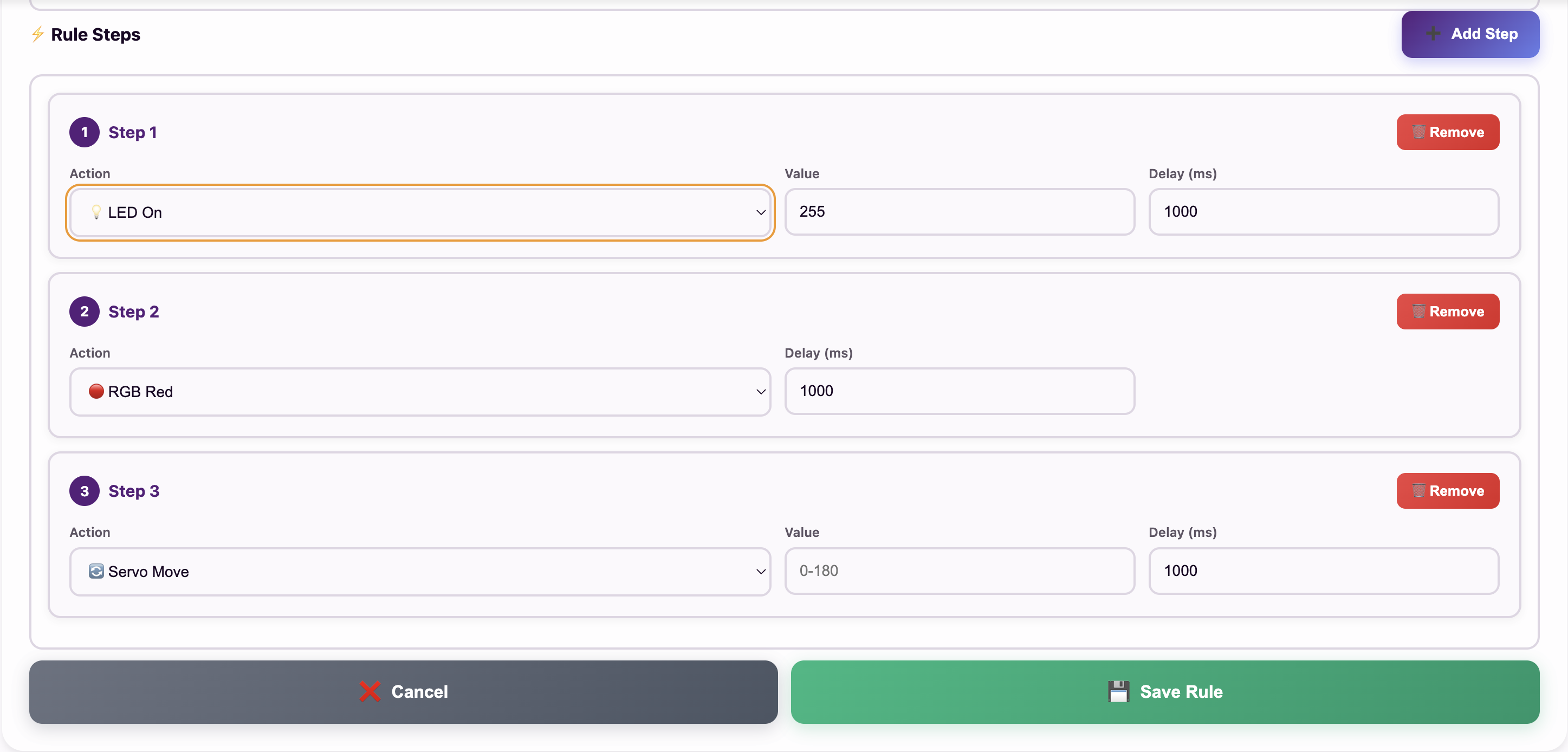
The Steps panel — click "+" to keep adding actions that will run one after the other.
What Is Inside One Step?
Every step has up to three fields:
Inside Each Step
- Action — what to do, chosen from a dropdown list (see the table below).
- Value — only appears for actions that need a number: LED brightness (0–255) or Servo angle (0–180).
- Delay (ms) — how many milliseconds to wait after this action before the next step runs. 1000 ms = 1 second.
The Full Action List
These are every action you can pick in a step:
| Component | Actions available | Needs a Value? |
|---|---|---|
| 💡 Single LED | LED On, LED Off | Yes — brightness 0–255 on LED On |
| 🌈 RGB LED | RGB Red, Green, Blue, Yellow, Purple, Cyan, White, Off | No — the colour is the action |
| 🔊 Buzzer | Buzzer On, Buzzer Off | No |
| ⚡ Relay | Relay On, Relay Off | No |
| 🔄 Servo | Servo Move | Yes — angle 0–180 |
| 📺 LCD | LCD Display | No — you type two lines of text instead |
Note on RGB: inside a rule step you choose from eight fixed colours. The free colour mixing you used in Week 5 is a dashboard control, not a rule step.
Note on LCD: when you pick LCD Display, the step swaps its Value and Delay boxes for two text lines of up to 16 characters each. You can drop live sensor readings straight into the text with wildcards such as {temp}, {humidity}, {light}, {soil} and {distance}.
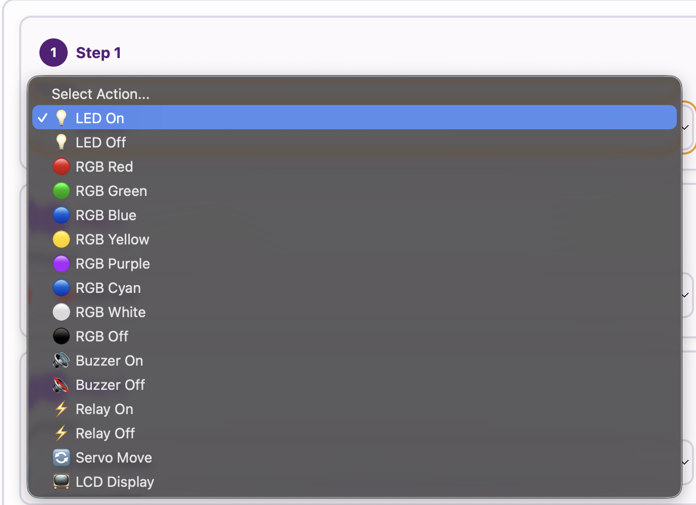
Inside a step — choose the component, set its value, set the delay. Here several steps are configured in sequence.
The Golden Rule of Delays
This is the single idea students get wrong most often, so read it twice:
A step's delay happens AFTER its action, not before. "Buzzer On, delay 1000" means "start the buzzer now, then wait one second before moving on" — which is how you make a beep that lasts one second.
So if you want something to stay on for 2 seconds and then switch off, you need two steps:
A Real Example: The Welcome Sequence
Here is a complete multi-step rule. It runs once when you save it, and again on every power-on if you enable it for startup:
Result: the LED comes on at full brightness, a one-second welcome beep plays, and the servo returns to its home position — automatically, in the right order, every time.
For Teachers
Steps are the concept that separates beginners from real automation builders. Push students to describe a system (a parking gate, a traffic light) as a sequence with waits rather than a single command. "What happens first, what happens next, and how long do we wait?" is exactly the mental model used in industrial PLC programming. The delay-after-action rule is worth demonstrating live: build the 2-step buzzer example, then deliberately swap the delays and let students hear the difference.
Activity: Build the Welcome Sequence
Time to build your first real rule. This one greets you when it runs.
Step-by-Step Instructions:
- Open the Rule Engine tab on the dashboard.
- Name the rule WelcomeSequence (names can be up to 20 characters).
- Loop Mode: choose ⏹️ No Loop.
- Step 1: Action → LED On, Value → 255, Delay → 1000.
- Click "+ Add Step". Step 2: Action → Buzzer On, Delay → 1000.
- Click "+ Add Step". Step 3: Action → Buzzer Off, Delay → 100.
- Press Save Rule and watch it run straight away! 🎉
- Press Start on the saved rule card to play it again.
What you built: a rule that turns the LED on, waits a second, beeps for a second, then goes silent — and stops. Because it is No Loop, nothing repeats and the dashboard controls stay yours.
Troubleshooting: if the Save button does nothing and a box turns red, check your Delay values — anything below 100 will be rejected.
Challenge: The Latching Relay Switch
Two Rules, One Relay
A latch is a switch that stays where you put it — like a light switch on a wall, as opposed to a doorbell that springs back. Build a latch out of two No Loop rules.
- Create a No Loop rule called RelayOn with one step: Action → Relay On, Delay → 100.
- Create a second No Loop rule called RelayOff with one step: Action → Relay Off, Delay → 100.
- Now use the Start button on each card to flip the relay on and off. Listen for the click.
Think about it: after RelayOn finishes, the rule has stopped running — yet the relay is still on. Why? What does that tell you about the difference between a rule running and an output holding its state?
Key Takeaways
✓ No Loop is a one-shot
It runs the whole sequence once — on save, on Start, and on boot if enabled for startup.
✓ Steps run in order
Up to 10 steps per rule, top to bottom, so one rule can drive several components.
✓ Delay comes after the action
To hold something on, put the wait on the step that switched it on.
✓ 100 ms is the floor
The dashboard rejects delays below 100 ms — use 100 for "as soon as possible".
Coming Up Next Week:
Week 23: Continuous Processing — Forever Loops — we take the brakes off and discover what happens when a rule never stops, and when two rules start fighting.