
Learning Objective
Control a digital output and understand PWM for analog-like control.
Hello World & PWM Dimming
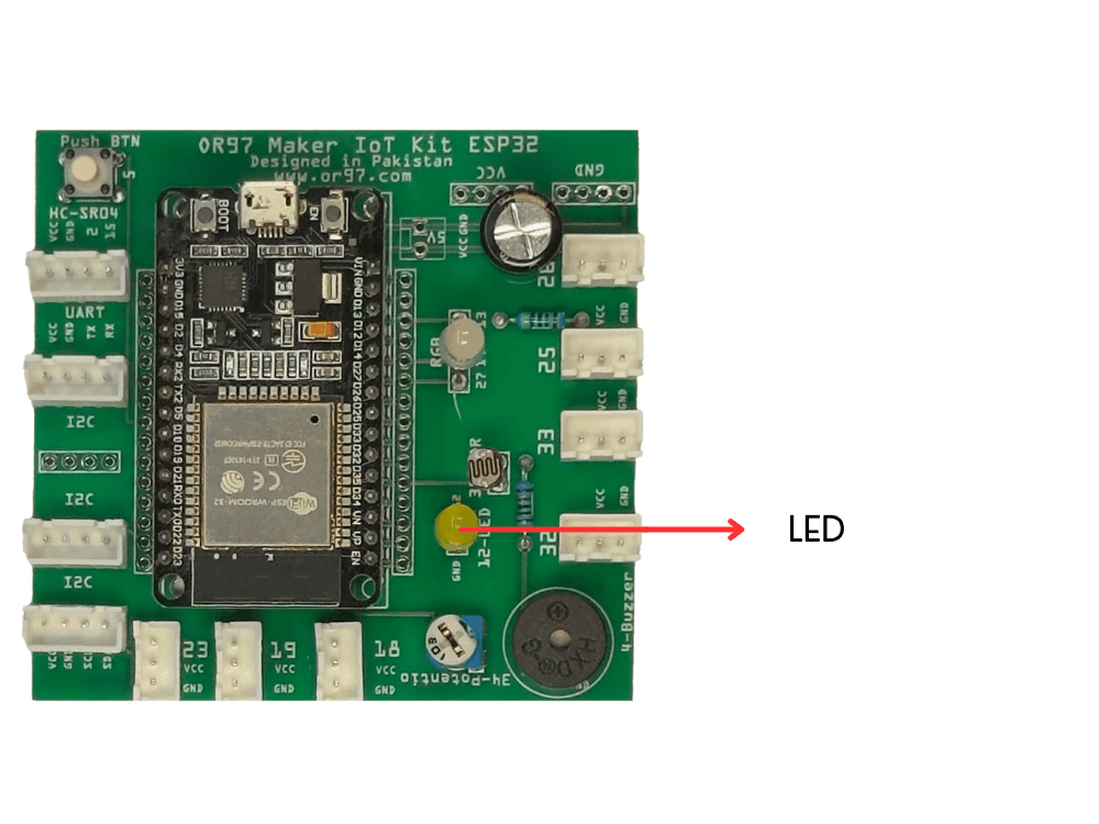
Hardware: MakerBuddy On-board Single LED
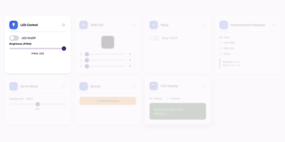
Dashboard: LED Control Card
Theory: Digital Logic
The Binary Language of Electronics
In the world of electronics, digital signals are the fundamental language. Unlike analog signals that can have any value in a range, digital signals exist in only two states: HIGH (represented as 1, typically 3.3V or 5V) and LOW(represented as 0, typically 0V). This binary system is the foundation of all computers and digital electronics. When we say an LED is "digital," we mean it can only be fully ON or fully OFF - there's no in-between state. Later in this lesson, we use PWM to create brightness levels.
How LEDs Work
LED stands for Light Emitting Diode. A diode is a special electronic component that allows electricity to flow in only one direction - this property is called polarity. An LED has two legs: the longer leg (or the leg marked with a flat edge on the plastic casing) is the positive side (anode) and the shorter leg is the negative side (cathode). If you connect an LED backwards, it won't light up (and could be damaged). When electricity flows through an LED in the correct direction, it emits light. Different materials inside the LED produce different colors - red LEDs use one semiconductor material, blue LEDs use another.
Digital Output on MakerBuddy
The single LED is already embedded and connected on your MakerBuddy IoT Board, so no wiring is needed. When you use the dashboard toggle, MakerBuddy changes the LED between ON and OFF almost instantly. This is a simple example of a digital output.
For Teachers
This is students' first experience with physical computing - controlling hardware with code. Emphasize that "Hello World" is traditionally the first program in any language and in electronics, blinking an LED serves the same purpose. The concept of binary (HIGH/LOW, 1/0, ON/OFF) connects to computer science fundamentals. If students have loose LEDs, demonstrate polarity by trying to light an LED both ways with a battery - only one orientation works. Discuss real-world applications: indicator lights, traffic signals, digital displays. The Morse code challenge makes the activity engaging while reinforcing timing and sequencing concepts.
For Parents
This week your child controls their first electronic component! The LED (Light Emitting Diode) teaches the concept of binary logic - things can be ON or OFF, with no in-between. This two-state system is the foundation of all digital technology, from your phone to traffic lights. Understanding polarity (positive and negative) is an important electrical safety concept. LEDs are everywhere in modern life: TV remotes use infrared LEDs, your car dashboard has indicator LEDs and even your phone screen uses millions of tiny LEDs. This lesson connects abstract programming concepts to tangible, visible results.
Theory: Pulse Width Modulation (PWM)
From ON/OFF to Dimming: The PWM Trick
PWM simulates analog output by rapidly switching between HIGH and LOW. The human eye perceives the average brightness.
Understanding Duty Cycle
Duty cycle is the percentage of time the signal is HIGH. 100% = fully on, 50% = half brightness, 0% = off. For example, at 50% duty cycle, the LED is ON for half the time and OFF for half, but switches so fast (thousands of times per second) that our eyes see it as half brightness.
PWM on the ESP32
The ESP32 has built-in PWM capabilities. On the MakerBuddy dashboard, the LED brightness slider sends PWM values from 0 (off) to 255 (full brightness). The slider maps to duty cycle percentage.
Real-World Applications
LED dimmers in homes, motor speed control, audio speakers, screen brightness on phones/laptops.
For Teachers
PWM bridges digital and analog concepts perfectly. It shows students how a digital system can simulate analog behavior by using time. This is a critical engineering concept!
For Parents
This is the exact same technology behind dimmer switches at home and the brightness control on your phone screen. PWM is a clever trick used everywhere in modern electronics.
Hands-On Activity: LED Control
Activity Duration: 15-20 minutes
Students will practice controlling the onboard LED, experiencing the direct connection between software interface and physical hardware. This foundational skill will be applied to more complex outputs later.
Step-by-Step Instructions:
- Locate the LED: Find the single LED already embedded on your MakerBuddy IoT Board. No connection is needed.
- Access LED Card: In the dashboard, scroll to the LED Control card. It should show a toggle switch and possibly a brightness slider.
- First Toggle: Click the toggle to turn the LED ON. Observe the physical LED light up instantly. Notice the visual feedback on the dashboard (the switch changes position/color).
- Toggle OFF: Click again to turn it OFF. Watch the LED extinguish immediately.
- Rapid Toggling: Try clicking the toggle rapidly several times. Notice how responsive the system is - there's almost no delay between your click and the LED's response.
- Test From Multiple Devices: If possible, open the dashboard on another device (another computer or phone on the same network) and control the LED from there. Multiple users can control the same hardware!
- Locate the Brightness Slider: In the LED card on the dashboard, find the brightness slider control below the toggle switch.
- Minimum Brightness: Slide to the lowest setting (around 10%). Notice the LED is very dim but still on.
- Half Brightness: Set to 50%. Compare the brightness visually to 100%.
- Full Brightness: Slide to 100%. The LED should be at maximum brightness.
- Smooth Dimming: Slowly slide from 0% to 100% and back. Notice the smooth, continuous change in brightness.
What Students Should Observe:
- Near-instantaneous response time between dashboard click and LED state change
- The visual feedback on the dashboard mirrors the physical state
- The connection between software command and hardware response
- Smooth brightness transitions
- The LED can be at any brightness level (not just ON/OFF)
- Faster slider changes create visible brightness variations
Challenge
Challenge 1: Brightness Target Practice
Try to set the LED to exactly 10% brightness, then 50%, then 100%. How different do they look?
Challenge 2: Dimming SOS Signal
Instead of just ON/OFF, send SOS using brightness levels:
- Dots: Dim flash (25% brightness for ~0.5s)
- Dashes: Bright flash (100% brightness for ~1.5s)
This is more subtle and harder to execute!
Challenge 3: Human Telegraph
Before wireless communication, Morse code was used to send messages via telegraph using short dots (·) and long dashes ( - ). Your challenge is to send an SOS distress signal using the LED toggle:
SOS: · · · - - - · · ·
Instructions:
- Dot (·): Quick flash - LED ON for ~0.5 seconds, then OFF
- Dash ( - ): Long flash - LED ON for ~1.5 seconds, then OFF
- Letter Gap: Pause ~1 second between letters (between the S and O and O and S)
- Pattern: 3 short, 3 long, 3 short
Bonus Challenge: Learn to send your initials in Morse code! Look up the Morse code alphabet online. Can you create a repeating pattern that spells your name?
Success Criteria: A classmate watching the LED (without seeing your screen) can recognize the SOS pattern.
Key Takeaways
✓ Digital Logic (HIGH/LOW)
Digital signals have only two states: HIGH (1, typically 3.3V) or LOW (0, 0V). This binary system is the foundation of all digital electronics and computing, enabling computers to process information using simple on/off switches.
✓ LED Operation
LEDs (Light Emitting Diodes) produce light when electricity flows through them in the correct direction. They're energy-efficient, long-lasting and used in everything from indicator lights to phone screens and car headlights.
✓ Polarity
Polarity means having a positive and negative side. LEDs and other diodes only work when connected correctly (positive to positive, negative to negative). Reversing polarity prevents the LED from lighting and can damage components.
✓ Real-time Control
IoT devices respond nearly instantaneously to commands sent over the network. The dashboard sends HTTP requests to the ESP32, which processes them in milliseconds, demonstrating the power of modern microcontrollers and network communication.
✓ PWM (Pulse Width Modulation)
PWM creates the illusion of analog output from a digital pin by rapidly switching between HIGH and LOW. The ratio of ON time to total time (duty cycle) determines the perceived brightness or speed.
✓ Duty Cycle
Duty cycle is expressed as a percentage (0-100%). At 50% duty cycle, the output is ON half the time. PWM is used everywhere: LED dimmers, motor controllers, and even audio speakers.
Coming Up Next Week:
Week 5: The Physics of Color (RGB LED)