
Learning Objective
Control high-power devices safely using a relay.
High Voltage Control (The Relay)
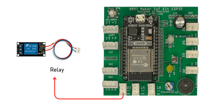
Hardware: Single Channel High Voltage Relay
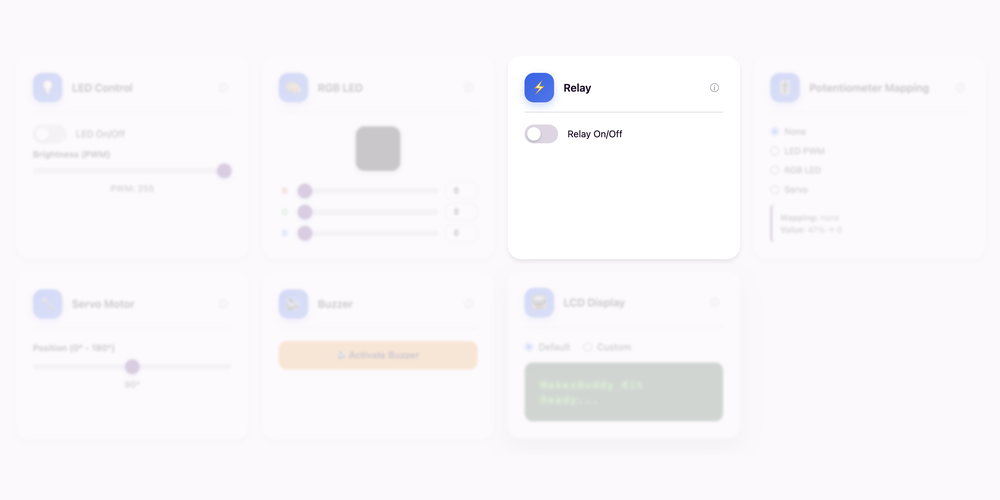
Dashboard: Relay Control Card
Theory: Relay Operation
Bridging Low and High Voltage Worlds
All our previous lessons controlled low-voltage components (LEDs, servos, buzzers) that run on 3.3-5V DC power. But what about controlling real-world appliances like fans, lights, heaters or motors that run on dangerous 120V or 240V AC power? You can't connect household AC directly to an ESP32 - it would instantly destroy the microcontroller! Enter the relay: an electromagnetic switch that allows low-voltage signals to safely control high-voltage circuits through complete electrical isolation.
How Relays Work: Electromagnets and Mechanical Switches
A relay uses an electromagnet to physically move a metal switch. When the ESP32 sends a small 3.3V signal to the relay coil, it creates a magnetic field that pulls a metal arm (armature) to close or open electrical contacts. These contacts can then switch completely separate high-voltage circuits. Think of it like a robot hand: your brain (ESP32) sends tiny nerve signals to your hand (relay), which then pushes a heavy switch (high-voltage contacts). The key is galvanic isolation - there's no electrical connection between the control side and the load side, only magnetic coupling. This means the dangerous high voltage can never "leak back" to damage your ESP32.
Technical Details: NO, NC and COM Terminals
Relays have three important terminals: COM (Common), NO (Normally Open) and NC (Normally Closed). In the default "off" state, COM is connected to NC. When activated, the electromagnet pulls the switch arm, disconnecting COM from NC and connecting COM to NO instead. For most IoT applications, you wire your load (fan, light, etc.) between COM and NO, so the circuit is "normally open" until the ESP32 activates the relay. The "click" you hear is the physical armature moving! Most relay modules include a flyback diode to protect against voltage spikes, an LED indicator showing relay state and support for loads up to 10A at 250V AC - plenty for household appliances.
Real-World Applications
Relays enable IoT to control the physical world! Smart home automation uses relays to turn lights, fans and heaters on/off remotely. Irrigation systems use relays to control water pumps and solenoid valves. Industrial automation uses relay banks to control motors, conveyor belts and heavy machinery. HVAC systemsuse relays to switch heating, cooling and ventilation equipment. Automatic backup generators use relays to detect power outages and start the generator. Even traffic lights traditionally used relays to switch high-power lamp circuits (though LEDs are replacing this now).
For Teachers
This lesson introduces electrical safety - a critical IoT concept. Emphasize that mixing low-voltage control circuits with high-voltage power circuits requires proper isolation. The relay provides both electrical isolation (no connection between sides) and current amplification (tiny ESP32 signal controls high-power loads). Have students LISTEN for the mechanical click - this demonstrates the relay is electromechanical, not purely electronic like transistors. Discuss why galvanic isolation matters: in case of a fault on the high-voltage side, the ESP32 remains safe. This is the bridge between hobby electronics and professional automation. Safety note: use only low-voltage demos in class - never connect actual AC power during student experiments unless you have proper electrical training and supervision.
For Parents
Your child is learning about relays - the safety device that allows smart home systems to control powerful appliances without risk. Relays are like remote-controlled switches: a small, safe signal from the smart device activates an electromagnet that physically flips a switch to control high-voltage power. This electrical isolation is crucial for safety - there's no direct connection between the smart controller and dangerous household voltage. Understanding relays helps students appreciate how smart thermostats control furnaces, how smart outlets control appliances and how home automation stays safe. This knowledge is fundamental to electrical engineering, building automation and industrial control systems.
Hands-On Activity: Relay Switching
Activity Duration: 20-25 minutes
Students will explore relay operation by manually controlling the relay through the dashboard and observing the mechanical switching action, LED indicators and terminal connections.
Step-by-Step Instructions:
- Connect the Relay Module: Connect the relay to its matching labelled connector on your MakerBuddy IoT Board. Identify the relay, its indicator LED and the low-voltage load connection.
- Open the Dashboard: Navigate to the Relay control card on your web interface. You should see an ON/OFF toggle button.
- Activate the Relay: Click the ON button. Listen carefully for the distinctive mechanical "click" sound as the electromagnet pulls the armature.
- Observe the LED Indicator: Notice the small red LED on the relay module lights up when activated. This shows current is flowing through the relay coil.
- Deactivate the Relay: Click the OFF button. Listen for another click as the spring returns the armature to its resting position. The LED should turn off.
- Rapid Switching Test: Toggle the relay ON and OFF several times in quick succession. Notice the consistent mechanical action - this demonstrates the relay can switch thousands of times reliably.
- Visual Inspection: While toggling the relay, carefully observe the blue relay component itself. Some clear-cased relays allow you to see the internal armature moving!
- Connect the Supplied Load: With teacher guidance, use the MakerBuddy board’s 2-pin power connector and the supplied 5V bulb or 5V fan as the relay load.
What Students Should Observe:
- Audible mechanical "click" sound when relay activates and deactivates
- Red LED indicator lights up only when relay is energized
- Immediate response to dashboard commands (very low latency)
- Consistent, repeatable switching action every time
- Physical movement inside the relay (if clear-cased module)
- Dashboard state accurately reflects relay status (ON/OFF)
Safety Note
Use only the supplied 5V bulb or 5V fan, powered through the MakerBuddy IoT Board’s 2-pin connector. Never connect 120V/220V mains electricity in a student activity. If an alternative load is needed, use a teacher-approved low-voltage load such as 12V—not household mains.
Challenge
Your Mission: Understanding Electrical Isolation and Safety
Explore the critical concepts of electrical safety, isolation and relay operation through hands-on experimentation and critical thinking!
Challenge 1: Timing the Relay
Measure relay switching speed and explore automation:
- Use a stopwatch or timer to measure how fast the relay responds to your dashboard command
- Record the time from clicking "ON" to hearing the "click" (should be under 100 milliseconds!)
- Test 10 times and calculate the average response time
- Try creating an automation rule: "IF Button = Pressed THEN Relay = ON" to control the relay with the physical button
- Compare manual control vs automated rule - which is faster?
Challenge 2: The Isolation Question
Answer these critical safety questions through research and reasoning:
- Why can't we connect 120/220V AC directly to the ESP32? (Hint: ESP32 runs on 3.3V DC - what happens if you apply 120/220V AC?)
- What does "galvanic isolation" mean? Research this term and explain it in your own words
- If the high-voltage side of the relay fails, can the fault damage the ESP32? Explain why or why not
- Why use electromagnets instead of electronic switching? Research why relays are still used despite being "old technology"
Challenge 3: Design a Smart Home Application
Design a complete relay-controlled system:
Choose ONE of these scenarios and design the automation rules:
- Automatic Fan: Turn on a ceiling fan when temperature exceeds 28°C
- Motion-Activated Lights: Turn on outdoor lights when PIR motion is detected
- Smart Irrigation: Activate a water pump when soil moisture drops below 30%
For your chosen scenario, specify:
- Which sensor to monitor
- What threshold value to use
- What device the relay controls
- The complete automation rule in IF-THEN format
- Why this threshold value makes sense for safety and efficiency
Discussion Questions:
- Why is the mechanical "click" sound actually a good thing? (It confirms the relay is working)
- What are the advantages of relays over purely electronic switches like transistors? (Complete isolation, can handle much higher currents)
- What are the disadvantages of relays? (Slower switching, mechanical wear, audible noise)
- Can a relay fail? What happens if the contacts weld together? (Safety hazard - load stays ON)
Bonus Challenge: Research and explain the difference between a relay and a solid-state relay (SSR). An SSR has no moving parts - how does it work? When would you choose an SSR over a traditional relay? (Answer: SSRs use semiconductors for switching, are silent and faster, but more expensive and generate more heat. Use SSRs for high-frequency switching applications like LED dimming or motor speed control.)
Key Takeaways
✓ Relay Operation
Relays are electromechanical switches that use low-voltage electromagnets to control high-voltage circuits through physical contact movement. When the ESP32 sends a 3.3V signal to the relay coil, it creates a magnetic field that pulls a metal armature to open or close electrical contacts, producing the characteristic "click" sound. This mechanical switching allows safe control of household appliances, industrial motors and other high-power devices from microcontroller signals.
✓ Electromagnets
Electromagnets are temporary magnets created when electric current flows through a wire coil, generating a magnetic field. The relay uses this principle: energizing the coil creates magnetism that attracts the metal armature and de-energizing it allows a spring to return the armature to rest position. This reversible magnetic action enables reliable, repeatable switching over millions of cycles, making electromagnets ideal for automated control applications.
✓ NO vs NC Terminals
Relay terminals include COM (Common), NO (Normally Open) and NC (Normally Closed) connections. In the default state, COM connects to NC. When activated, the electromagnet breaks the COM-NC connection and creates a COM-NO connection instead. Most IoT applications use the NO configuration, wiring loads between COM and NO so circuits are "off by default" and only energize when the relay is activated, providing fail-safe operation.
✓ Galvanic Isolation
Galvanic isolation means there is no direct electrical connection between the control circuit (ESP32) and the load circuit (high-voltage appliance) - only magnetic coupling through the electromagnet. This complete electrical separation is critical for safety: if the high-voltage side experiences a fault or short circuit, the dangerous voltage cannot "leak back" to damage the microcontroller or harm users. This makes relays essential safety devices in professional automation and smart home systems.
Coming Up Next Week:
Week 16: Term 2 Project — The Data Logger