
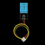
DHT11
Temperature 0–50°C · Humidity 20–90%
Hardware reference
Review the current MakerBuddy ESP32 hardware map, sensor acquisition, actuator behavior, networking, persistence, timing and security boundaries.
MakerBuddy is an ESP32-based educational and prototyping platform. This page reflects the current MakerBuddy_dev firmware 2.3 source and its WebApp/Chrome 2.5 and MobileApp 1.5.0 clients.
| Area | Current implementation |
|---|---|
| Controller | ESP32, dual-core 32-bit Xtensa LX6, up to 240 MHz |
| Memory | 520 KB SRAM, 448 KB ROM |
| Flash | 4 MB SPI flash |
| Wireless | 2.4 GHz Wi-Fi 802.11 b/g/n and Bluetooth 4.2/BLE capability |
| Interfaces used | Digital I/O, ADC1, PWM/LEDC, I2C and 1-Wire |
| Local control | HTTP REST on port 80 and WebSocket at /ws |
| Device persistence | ESP32 Preferences/NVS namespace iot-kit |
| Typical input power | 5 V through USB-C, with onboard 3.3 V and 5 V rails |
The current MakerBuddy runtime uses Wi-Fi, not Bluetooth, for dashboard communication. Exact ESP32 modules and MakerBuddy PCB revisions can vary; board markings and the schematic for the physical revision remain authoritative.
| Device | GPIO | Firmware acquisition and representation |
|---|---|---|
| Push button / Wi-Fi reset | 5 | INPUT_PULLUP; active low; reports pressed/not pressed |
| LDR | 35 | Four ADC reads averaged and mapped to 0–100 |
| Potentiometer | 34 | Four ADC reads averaged and mapped to 0–100 |
| MQ-2 gas sensor | 33 | Four ADC reads averaged and mapped to 0–100 |
| Soil moisture | 32 | Four ADC reads averaged; raw 0–4095 plus calibrated 0–100 |
| HC-SR04 echo | 2 | Pulse measurement with 24 ms timeout; input is level-shifted for 3.3 V logic on the reference board |
| HC-SR04 trigger | 15 | 10 µs digital trigger pulse |
| DS18B20 | 26 | 1-Wire temperature in °C; disconnected reads become 0.0 |
| DHT11 | 25 | Temperature and humidity; invalid/NaN reads become 0.0 |
| PIR motion | 18 | Active-high digital motion input |
GPIO 32–35 are ADC1-capable, so these analog readings remain available while Wi-Fi is active. GPIO 2, 5, 12 and 15 have ESP32 boot/input implications; do not repurpose them without checking the board and boot-strapping behavior.
Soil calibration defaults to dry raw 3000 and wet raw 1200. The values are clamped to 0–4095 and calibrated moisture returns 0 if both endpoints are equal.
Ultrasonic readings are accepted only from 2 to 500 cm. An invalid sample retains the previous valid distance; before the first valid result, the value is 999 cm.
| Device | GPIO | Firmware behavior |
|---|---|---|
| Single LED | 12 | analogWrite; state, 0–255 PWM and optional 500 ms blink cadence |
| RGB red | 13 | Inverted analogWrite output |
| RGB green | 14 | Inverted analogWrite output |
| RGB blue | 27 | Inverted analogWrite output |
| Active buzzer | 4 | Digital output; a direct dashboard/API command pulses for 500 ms |
| Servo | 19 | Pin-based LEDC at 50 Hz, 16-bit, 500–2500 µs mapped over 0–180° |
| Relay | 23 | Immediate digital state; requested delay fields are ignored |
| LCD SDA | 21 | I2C data for 1602 display |
| LCD SCL | 22 | I2C clock for 1602 display; address 0x27 |
RGB values exposed by the APIs are conventional 0–255 intensities. The physical PWM is inverted as 255 - value because the current design uses a common-anode RGB LED.
Never connect classroom experiments directly to mains electricity. Use the relay only with a suitable low-voltage educational load unless a qualified professional has designed and supervised the installation.
Component reference
Identify each supported module before connecting it, then use the surrounding pin maps and API guidance as you build.
Temperature 0–50°C · Humidity 20–90%
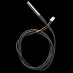
Waterproof temperature probe · −55 to 125°C
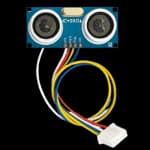
Ultrasonic distance sensor · 2–400 cm
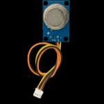
Gas and smoke sensing · Analog output
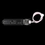
Capacitive sensing · Analog output
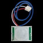
Infrared motion detection · Digital output
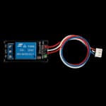
5 V relay module · Isolated switching
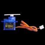
Position control · 0–180°
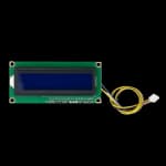
16 × 2 character display · I2C interface
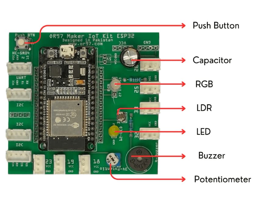
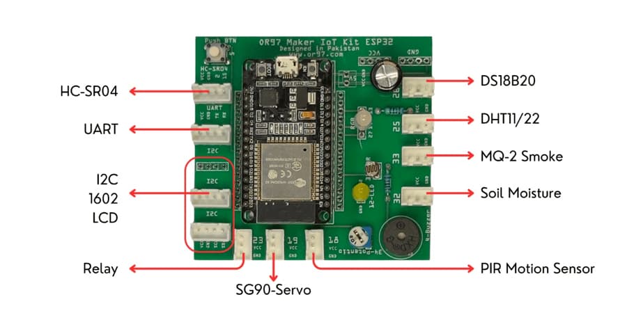
The 16×2 I2C LCD has default rotation and custom-text modes. Firmware checks both custom lines against the physical 16-column limit and supports these live substitutions:
{temp} {humidity} {ds18b20} {light} {gas}
{soil} {distance} {pot} {motion} {button}
Validation uses each wildcard's currently rendered value, not the source token length. This makes a template such as Temp: {temp} practical, but a later, wider sensor value can make an edited template exceed the display width. Sequence LCD strings are stored in 17-byte fields; recognized wildcards are internally encoded to preserve the persisted binary layout.
Ticker callbacks set flags only; sensor, display, persistence and network work runs in the main loop.
| Work | Cadence or trigger |
|---|---|
| Sensor acquisition | Every 1 second |
| WebSocket telemetry | At most every 2 seconds |
| LCD update opportunity | Every 100 ms |
| Sensor-screen rotation | Every 3 seconds |
| Wi-Fi/IP, device-name and custom screens | Every 5 seconds |
| LED blink state | Every 500 ms |
| Sequence processing | Every loop unless a deferred sequence save is pending |
| Stale WebSocket cleanup | Every 10 seconds |
Provisioning, Wi-Fi connection attempts, current buzzer pulses and OTA contain blocking paths. They are exceptions to the normal flag-driven design.
On first provisioning, firmware derives MakerBuddy_XXXX from the last two MAC-address bytes, protects the access point with 12345678, and runs wildcard captive DNS at 192.168.4.1. The setup form stores the normalized device name, SSID and password, then restarts.
In station mode, the board attempts three connection batches with up to 20 waits of 500 ms per batch. A successful connection starts the HTTP/WebSocket server and, when a device name exists, advertises <device-name>.local through mDNS. On failure, the firmware disables Wi-Fi and continues standalone rather than falling back automatically to provisioning.
Holding GPIO 5 for 10 seconds clears only the saved network credentials and restores the default LCD mode before restart. Other preferences remain.
All device application traffic is plain HTTP/WS. There is no HTTPS/WSS mode in the current firmware.
The ESP32 stores and executes up to 10 sequences with up to 10 steps each. Supported step actions cover LED on/off/PWM, eight RGB presets/off, buzzer and relay on/off, servo position, and LCD display.
Automation priority is Condition → Timer → Forever → None. A running rule locks only the device used by its current step against lower-priority rules. A timer waiting for its next interval owns no actuator. Condition rules debounce a matching expression for 300 ms; if the condition becomes false mid-cycle, the rule finishes the current cycle before stopping so cleanup actions can run.
Each sensor expression supports a threshold or two comparisons combined with AND/OR. Firmware 2.3 also supports an optional second sensor expression, with another AND/OR joining both complete expressions. Equality is approximate, with an absolute difference below 0.1.
See Documentation for the REST and compact WebSocket sequence formats.
All saved values use the ESP32 Preferences namespace iot-kit.
| Keys | Stored data |
|---|---|
wifi_ssid, wifi_password, deviceName | Network and device identity |
lcdDefault, customText1, customText2 | LCD state |
potMappingId | Numeric potentiometer mode; legacy potMapping is migrated |
soilDry, soilWet | Soil calibration |
seqCount | Active sequence count |
seq_0 … seq_9 | Compact binary sequence records |
seqc_0 … seqc_9 | Versioned second-condition extensions |
seqms_0 … seqms_9 | Manually stopped flags |
seqBlob | Legacy full-array format, migrated and removed after a successful load |
Sequence writes use dirty/remove bitmasks so only affected slots are rewritten. Runtime fields are reset when records load, and orphaned keys beyond the valid count are removed. The structures in MakerBuddyTypes.h participate in binary storage; reordering or resizing fields requires a deliberate migration.
Potentiometer mapping is loaded or migrated during boot and then deliberately forced to none. Users must select a target again after each restart.
| Library | Purpose |
|---|---|
| ESPAsyncWebServer | Asynchronous HTTP and WebSocket server |
| AsyncTCP | ESP32 asynchronous TCP transport |
| ArduinoJson 6.x | REST and compact WebSocket JSON |
| DHT sensor library | DHT11 acquisition |
| Adafruit Unified Sensor | DHT dependency |
| OneWire | 1-Wire transport |
| DallasTemperature | DS18B20 acquisition |
| LiquidCrystal_I2C | 1602 I2C LCD control |
The current source does not use ESP32Servo; servo PWM is generated directly with the Arduino-ESP32 pin-based LEDC API.
lib_deps =
  me-no-dev/ESPAsyncWebServer
  me-no-dev/AsyncTCP
  bblanchon/ArduinoJson@^6.21.3
  adafruit/DHT sensor library
  adafruit/Adafruit Unified Sensor
  paulstoffregen/OneWire
  milesburton/DallasTemperature
marcoschwartz/LiquidCrystal_I2CThe clients check http://app.makerbuddy.cc/firmware.json and pass a selected binary URL to the board. The firmware then:
iot-kit Preferences namespace.Configuration is cleared before download success is known. A failed OTA therefore still erases Wi-Fi, device identity, rule, calibration, LCD and mapping settings; it also leaves the periodic tickers detached until reboot. OTA URLs are neither origin-restricted nor signature-verified in firmware 2.3.
MakerBuddy firmware 2.3 is designed for a trusted local learning network:
Do not expose port 80 to the public internet. Isolate classroom devices where appropriate, do not use production credentials on the MakerBuddy network, and do not use its readings or controls for medical, industrial, life-critical or certified safety decisions.
The current code supports DHT11, DS18B20, LDR, MQ-2, capacitive soil moisture, HC-SR04, PIR motion, push-button and potentiometer inputs. It controls the onboard single LED, common-anode RGB LED, active buzzer, single-channel relay, SG90-class servo and 1602 I2C LCD.
Third-party modules can differ in voltage, current, signal polarity and connector order even when the plugs look compatible. Check the module datasheet, board labels and exact MakerBuddy PCB revision before connecting an unlisted part.
Build with MakerBuddy
Start with prepared hardware, see results quickly, and keep going all the way into code.