
Learning Objective
Read variable voltage, understand analog signals, and use direct mapping to control outputs.
Analog Inputs & Direct Mapping
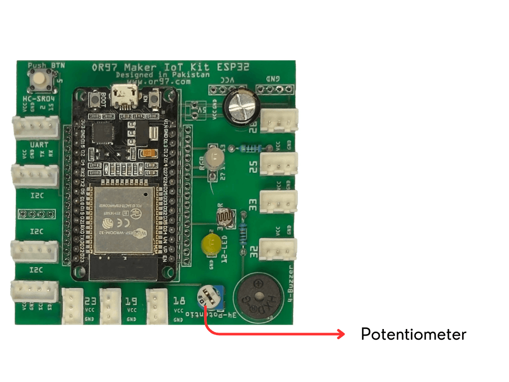
Hardware: MakerBuddy On-board Potentiometer
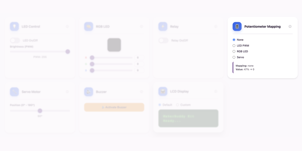
Dashboard: Potentiometer Mapping Card
Theory: Analog Signals and Variable Resistors
From Digital to Analog: Reading a Range of Values
Last week we learned about digital inputs that can only be ON or OFF (1 or 0). This week, we're exploring analog inputs that can read a continuous range of values! Think of it like this: a light switch is digital (on or off), but a dimmer switch is analog (any brightness level from 0% to 100%).
How Potentiometers Work
A potentiometer (or "pot" for short) is a variable resistor with three connections. As you turn the knob, a wiper inside moves along a resistive track, changing the resistance and therefore the voltage output. The ESP32 reads this voltage using its Analog-to-Digital Converter (ADC), which converts the analog voltage (0-3.3V) into a digital number (0-4095).
Understanding Resolution: 12-bit Precision
The ESP32 has a 12-bit ADC, meaning it divides the voltage range into 4096 steps (212= 4096). This gives us incredible precision! For easier use, MakerBuddy maps these values to 0-100 on the dashboard, but the full 0-4095 range is available for advanced projects. This resolution is what allows us to detect tiny changes in position.
Real-World Applications
Potentiometers are everywhere: volume knobs on speakers, brightness controls on monitors, joystick controllers in game consoles and even the gas pedal in some cars! Any time you need to adjust something smoothly across a range, potentiometers are the answer.
For Teachers
This lesson introduces the critical concept of analog vs digital signals. Use concrete examples: a staircase (digital - discrete steps) vs a ramp (analog - continuous). Demonstrate the mapping concept: raw ADC values (0-4095) are mathematical representations that can be scaled to any range (0-100%, 0-360°, etc.). This prepares students for future mapping lessons. Have students plot potentiometer readings on graph paper to visualize the continuous nature of analog data.
For Parents
This week your child learns about analog signals - the foundation for reading sensors that measure things in ranges rather than simple on/off states. This concept is essential for understanding how devices measure temperature, light levels, position and more. The potentiometer is a hands-on tool that makes abstract concepts (like variable resistance and voltage) tangible. Understanding analog-to-digital conversion is fundamental to modern electronics and computing.
Theory: Direct Mapping - One Input, Many Outputs
What is Mapping?
Mapping is converting a value from one range to another. For example, the potentiometer reads 0-4095 (raw ADC), but we want to control an LED brightness (0-255) or a servo angle (0-180°). The concept is proportional/linear mapping: if the pot is at 50%, the LED should be at 50% brightness and the servo at 90°.
The Mapping Formula
The mapping formula is: output = (input - inputMin) / (inputMax - inputMin) × (outputMax - outputMin) + outputMin.
Example: Potentiometer reads 2048 (out of 4095).
Mapping to LED brightness (0-255): 2048/4095 × 255 ≈ 128 (half brightness).
Mapping to servo angle (0-180°): 2048/4095 × 180 ≈ 90° (middle position).
Direct vs Indirect Mapping
Direct mapping means the output changes in real-time as the input changes. When you turn the knob, the LED brightness and servo position change instantly and proportionally. This is different from threshold-based control (which we'll learn later) where the output only changes when a value crosses a boundary.
Real-World Applications
Volume knobs controlling speaker output, steering wheels mapping rotation to wheel angle, guitar tuning pegs, gas pedals mapping foot pressure to engine speed.
For Teachers
This lesson connects math (proportions, linear functions) to physical computing. Have students calculate expected output values before testing to reinforce the mapping formula.
For Parents
Direct mapping is how most physical controls work - from volume knobs to car steering. Understanding this principle helps students see the math behind everyday technology.
Hands-On Activity: Potentiometer Reading
Activity Duration: 20-25 minutes
Students will explore analog input reading by rotating the potentiometer and observing how smoothly values change on the dashboard.
Step-by-Step Instructions:
- Locate the Potentiometer: Find the blue rotating knob already embedded and connected on your MakerBuddy IoT Board. No wiring is needed.
- Open the Dashboard: Navigate to the Potentiometer card on your web interface.
- Turn Fully Left: Rotate the knob all the way counter-clockwise. Note the minimum value (should be close to 0 or 0%).
- Turn Fully Right: Rotate the knob all the way clockwise. Note the maximum value (should be close to 100%).
- Smooth Rotation: Slowly turn the knob from left to right while watching the value change. Notice how it changes continuously, not in jumps.
- Precision Test: Try to set the potentiometer to exactly 25, then 50, then 75. How precise can you be?
- Record Data: Create a table showing the value at different positions: fully left, 1/4 turn, halfway, 3/4 turn, fully right.
- Choose LED Mapping: On the dashboard, find the Potentiometer Mapping card and select LED.
- Test LED Control: Slowly turn the potentiometer and watch the LED brightness change in real-time. At 0% pot = LED off. At 100% pot = LED full brightness.
- Choose Servo Mapping: Select Servo instead to try direct servo control.
- Test Servo Control: Turn the potentiometer and watch the servo motor move proportionally. Full left = 0°, full right = 180°.
- One Mapping at a Time: Choose one output—LED, RGB or Servo—then turn the knob and observe the result.
What Students Should Observe:
- Smooth, continuous value changes (not jumps like the button)
- Direct correlation between knob position and displayed value
- Values ranging from 0 to 100 on the dashboard
- Direct proportional relationship between knob position and outputs
- One selected output responding smoothly to a single input
- Smooth continuous control of multiple outputs
Challenge
Your Mission: Precision Challenge
Test your precision and learn about analog control with these challenges!
Challenge 1: Precision Mapping
Try to dial in these exact values as quickly as possible (within ±1):
- Exactly 25
- Exactly 50
- Exactly 75
After hitting the potentiometer target, predict what the LED brightness percentage and servo angle should be. Were your predictions correct?
Challenge 2: The Mood Controller
Design a 'mood' for each zone of the potentiometer:
- Zone 1 (0-25%): "Calm" - dim LED, servo at rest (0°).
- Zone 2 (25-50%): "Alert" - medium LED, servo at 90°.
- Zone 3 (50-75%): "Excited" - bright LED, servo at 135°.
- Zone 4 (75-100%): "Maximum" - full LED, servo at 180°.
Test each zone by setting the potentiometer and verifying the outputs match your predictions.
Bonus: Reverse Mapping: Can you figure out the math for reverse mapping? If the servo is at 45°, what should the potentiometer percentage be? (Answer: 45/180 × 100 = 25%)
Key Takeaways
✓ Analog vs Digital
Digital signals have only two states (HIGH/LOW), while analog signals can have any value within a range. Analog inputs allow us to read continuous measurements like position, temperature and light intensity with precision.
✓ Variable Resistors
Potentiometers are variable resistors that change resistance based on knob position. As resistance changes, the output voltage changes, allowing us to create adjustable controls for any application.
✓ ADC (Analog-Digital Converter)
The ESP32's 12-bit ADC converts analog voltages (0-3.3V) into digital numbers (0-4095). This conversion allows the digital microcontroller to understand and process analog sensor data from the real world.
✓ Resolution
12-bit resolution provides 4096 distinct values, giving us very fine control and measurement precision. Higher bit depth means more detailed readings and smoother control of outputs.
✓ Direct Mapping
Direct mapping converts values from one range to another proportionally. One input (potentiometer) can simultaneously control multiple outputs (LED, servo) by mapping to different ranges.
✓ Proportional Control
Proportional control means the output changes smoothly and continuously in response to input changes. This is the foundation of many real-world control systems, from cruise control to thermostat regulation.
Coming Up Next Week:
Week 10: Atmospheric Sensing (DHT11)