Basic electronics is the study of how electricity flows around a circuit, and how parts such as resistors, LEDs, buttons and sensors control that flow. Before your first circuit you need twelve ideas: the circuit, voltage, current, resistance, Ohm's law, power, series and parallel, polarity and ground, digital signals, analog signals, PWM, and input, process, output.
Each idea below comes in plain words, with the numbers that matter and a place to watch it happen on the MakerBuddy IoT Kit's built-in blue light, button, light sensor and knob. You also get a worked LED resistor sum, a 45-minute lesson and the common beginner mistakes.
The 12 basic electronics ideas at a glance
- 1
Circuit
electricity flows only around a complete loop.
- 2
Voltage
the push that moves electric charge, measured in volts (V).
- 3
Current
the flow of charge, measured in amps (A) or milliamps (mA).
- 4
Resistance
how strongly a part slows the flow, measured in ohms (Ω).
- 5
Ohm's law
voltage equals current times resistance, V = I × R.
- 6
Power
how fast energy is used, P = V × I, measured in watts (W).
- 7
Series and parallel
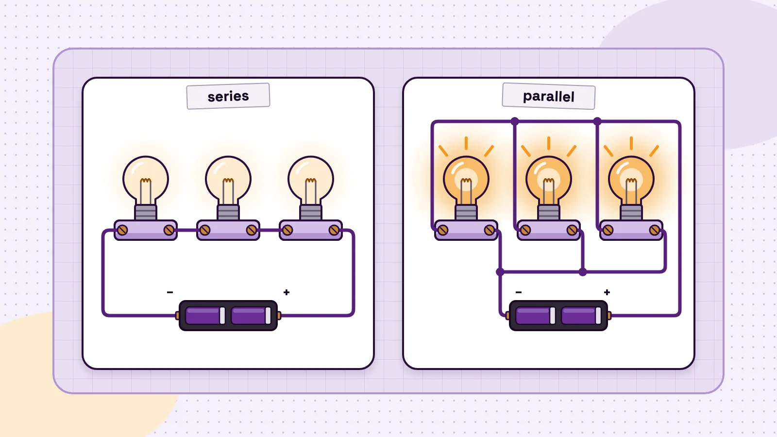
parts in a line share one current; parts side by side share one voltage.
- 8
Polarity and ground
some parts work only one way round, and ground (GND) is the 0 V point everything returns to.
- 9
Digital signal
two states, HIGH and LOW, like a button pressed or released.
- 10
Analog signal
any value in a range, like the voltage from a light sensor.
- 11
PWM
switching a pin on and off very fast, so an LED looks dimmer.
- 12
Input, process, output
sensors notice, a controller decides, outputs act.
Every idea links to something you can see or test on the MakerBuddy IoT Kit V1.0, a board built around an ESP32 DevKit with six parts that need no wiring.
Ideas 1 to 4: circuit, voltage, current and resistance
1. A circuit is a complete loop
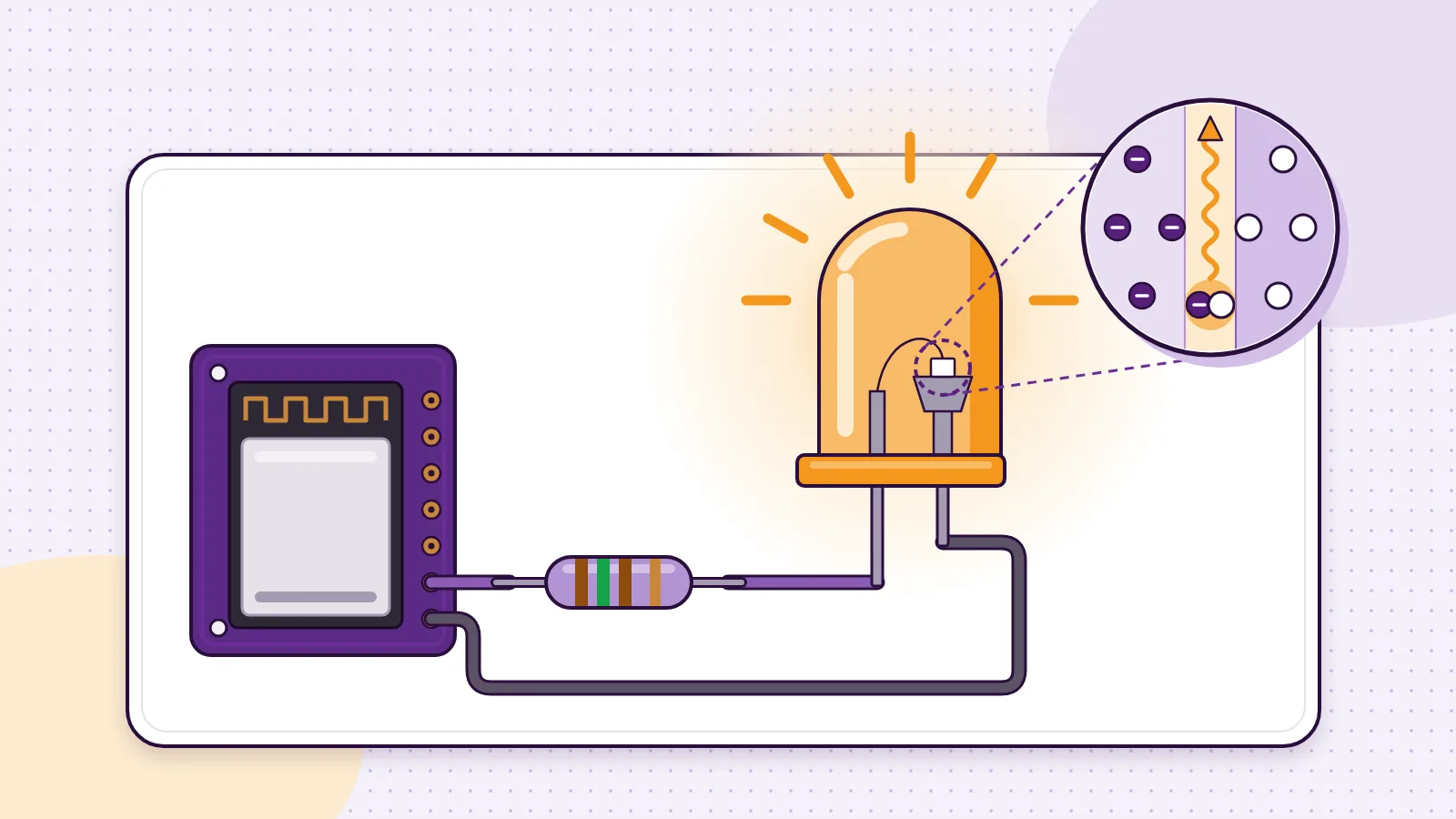
Electricity only does useful work when it has a full path: out of the supply, through the parts and back. SparkFun's guide to what a circuit is (opens in a new tab) calls this path a circuit. Break the loop anywhere and you have an open circuit: nothing flows, nothing works, and nothing is harmed. A switch is a break you open and close on purpose.
A short circuit is the dangerous opposite: a wire straight from positive to negative that skips the parts. SparkFun warns it can burn up the wire, damage the power supply or drain the battery. More in open, closed and short circuits explained.
On MakerBuddy: the push button on pin 5 is a switch that closes a loop to ground. Hold it for about 3 seconds and the Push Button card shows Pressed. The board checks the button once a second, so a quick tap can be missed, as Lesson 6 explains.
2. Voltage is the push
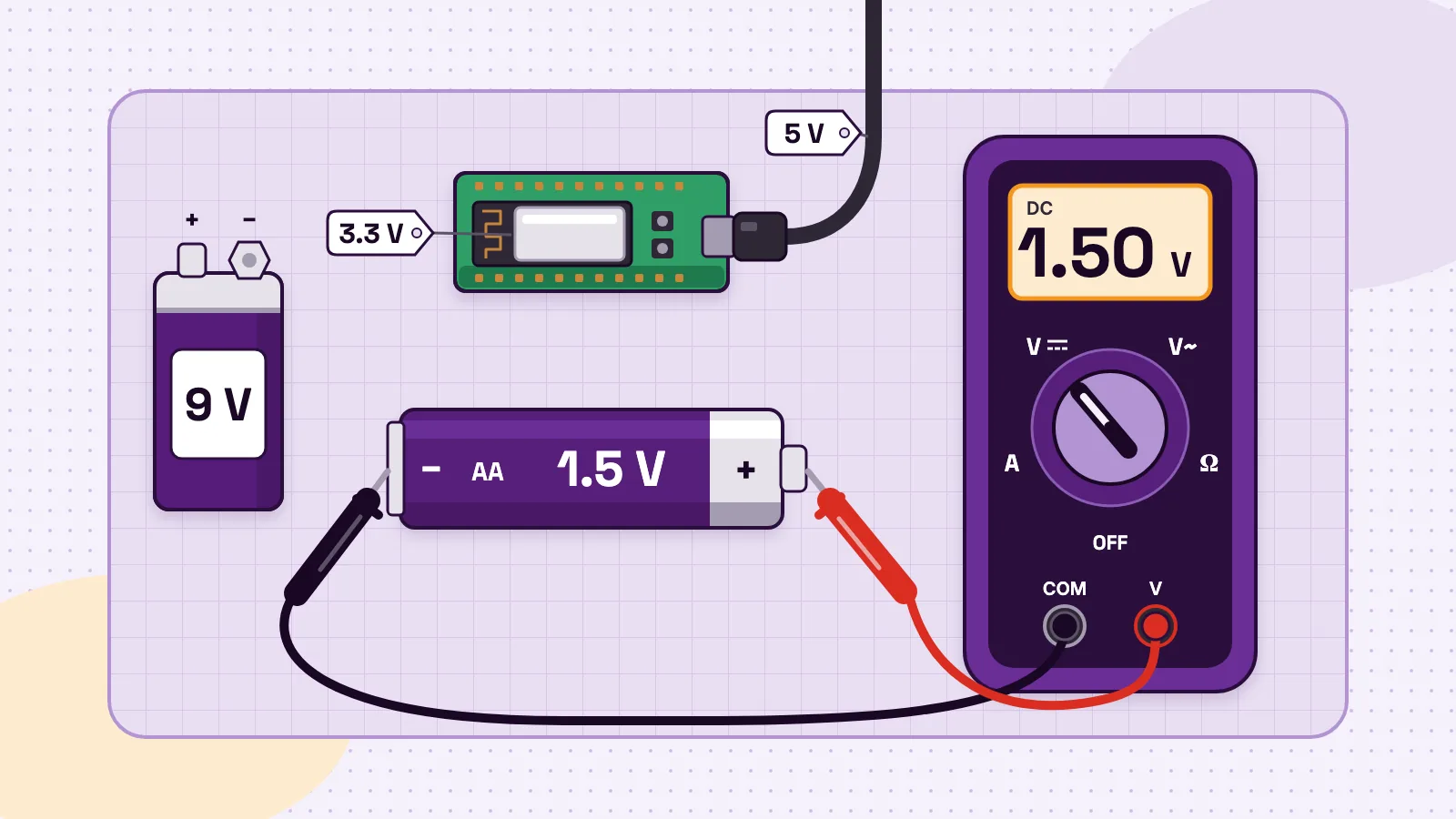
Voltage is the difference in electrical pressure between two points, measured in volts. In SparkFun's water-tank comparison (opens in a new tab), the water is the charge, the pressure is the voltage, the flow is the current and the width of the hose is the resistance. See voltage, explained simply.
On MakerBuddy: the board runs on 5 V from a USB cable, and the ESP32 DevKit turns it into the 3.3 V its chip needs, as the technical details explain. A pin set HIGH sits close to 3.3 V, and a pin set LOW close to 0 V.
Wall sockets carry far more: 120 V in North America and 220 to 240 V in Europe, says SparkFun's AC and DC guide (opens in a new tab). This guide stays at 5 V or below.
3. Current is the flow
Current is how much charge flows past a point each second, measured in amps. Small parts use milliamps: 1 mA is a thousandth of an amp. Current does the work, and too much of it makes parts hot. Read more in electric current, amps and flow.
Every part has a limit. The Kingbright WP7113ID datasheet (opens in a new tab), for a common 5 mm red LED, allows at most 30 mA. The ESP32 datasheet (opens in a new tab) gives about 40 mA as the typical current one pin can supply, falling towards 29 mA as more pins share the load. That is plenty for an LED, but Arduino's guide to motors and transistors (opens in a new tab) notes that most motors need more current or voltage than a pin can give.
On MakerBuddy: switch on the LED Control card. The blue light on pin 12 glows only while current flows through it.
4. Resistance slows the flow
Resistance is how strongly something resists current, measured in ohms (Ω). SparkFun (opens in a new tab) defines one ohm as the resistance that lets 1 volt push 1 amp. A resistor either limits current or turns a change in resistance into a change in voltage. See what a resistor actually does.
Some resistors change on purpose. A potentiometer changes as you turn it; see how a potentiometer works. A light-dependent resistor (LDR) changes with light. Adafruit's photocell guide (opens in a new tab) gives about 200 kΩ in the dark and 10 kΩ at 10 lux, and warns that cells can differ by 50% or more. So an LDR answers "is it getting dark?" well and "exactly how bright?" badly.
On MakerBuddy: cover the light sensor on pin 35 and its resistance rises; shine a torch on it and its resistance falls. The Light Level card shows low numbers in the dark and high numbers in bright light. Lesson 7 has the full activity.
Idea 5: Ohm's law, with a worked LED resistor example
Ohm's law ties the first four ideas together: V = I × R, which also gives I = V ÷ R and R = V ÷ I. Know two and you can find the third. SparkFun's Ohm's law tutorial (opens in a new tab) uses the same letters.
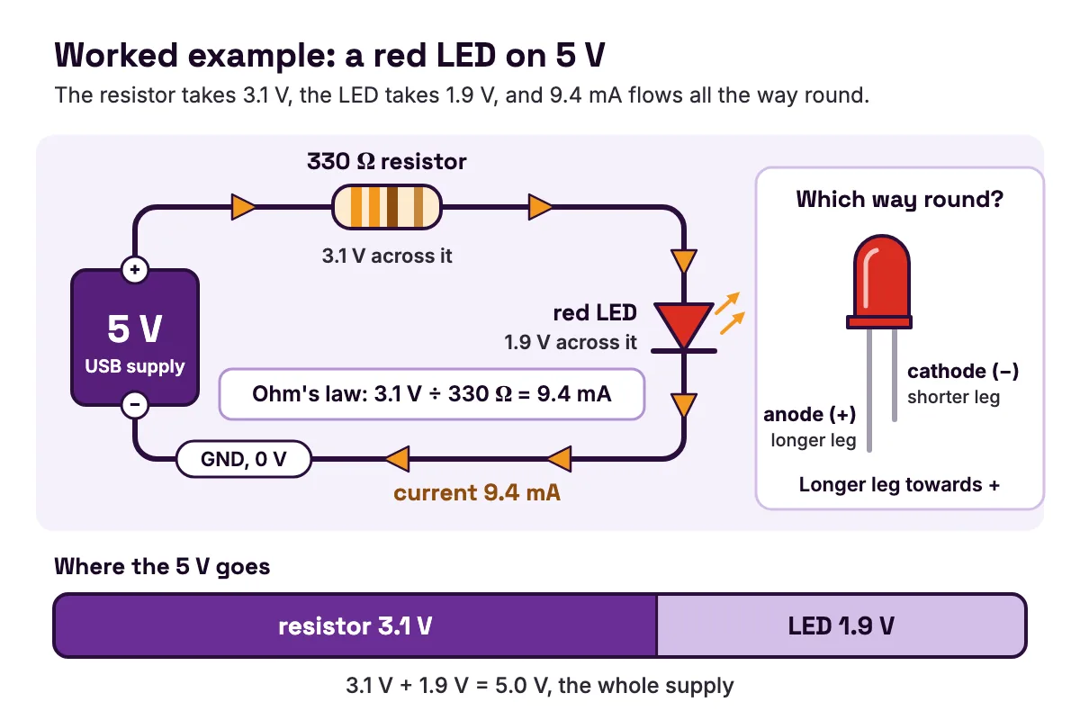
Its first real job is choosing a resistor for an LED. A glowing LED uses up a fairly fixed slice of the supply voltage, called its forward voltage. The rest drops across the resistor, and the resistor's value sets the current:
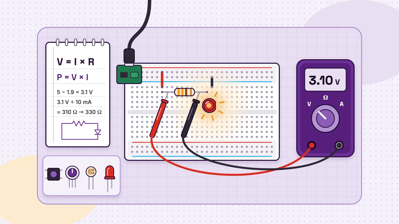
Resistor = (supply voltage − LED forward voltage) ÷ the current you want
Worked example: a red LED on 5 V USB power
The Kingbright WP7113ID datasheet (opens in a new tab) gives a forward voltage of 1.9 V typical and 2.3 V maximum at 10 mA, and a 30 mA limit. Aim for 10 mA.
- 1
Voltage left for the resistor
5.0 V − 1.9 V = 3.1 V.
- 2
Resistance
3.1 V ÷ 0.010 A = 310 Ω.
- 3
Round up to a value you can buy
330 Ω. Rounding up lowers the current, which is the safe direction. SparkFun's LED tutorial (opens in a new tab) also calls 330 Ω a good value for most LEDs.
- 4
Check the current
3.1 V ÷ 330 Ω = 0.0094 A, or 9.4 mA. That is under the 30 mA limit.
- 5
Check the dimmest case
if the LED drops 2.3 V, then 2.7 V ÷ 330 Ω = 8.2 mA. Still clearly lit.
- 6
Check the resistor's power
3.1 V × 0.0094 A = 0.029 W. SparkFun's electric power tutorial (opens in a new tab) says most resistors are rated for 1/8 W to 1/2 W, so a small one copes.
| Supply | Voltage left for the resistor | Exact value for 10 mA | A common value just above | Current with that resistor |
|---|---|---|---|---|
| 3.3 V (an ESP32 pin) | 1.4 V | 140 Ω | 150 Ω | 9.3 mA |
| 5 V (USB) | 3.1 V | 310 Ω | 330 Ω | 9.4 mA |
| 9 V (battery) | 7.1 V | 710 Ω | 820 Ω | 8.7 mA |
- Supply
- 3.3 V (an ESP32 pin)
- Voltage left for the resistor
- 1.4 V
- Exact value for 10 mA
- 140 Ω
- A common value just above
- 150 Ω
- Current with that resistor
- 9.3 mA
- Supply
- 5 V (USB)
- Voltage left for the resistor
- 3.1 V
- Exact value for 10 mA
- 310 Ω
- A common value just above
- 330 Ω
- Current with that resistor
- 9.4 mA
- Supply
- 9 V (battery)
- Voltage left for the resistor
- 7.1 V
- Exact value for 10 mA
- 710 Ω
- A common value just above
- 820 Ω
- Current with that resistor
- 8.7 mA
Table note: every row uses the 1.9 V forward voltage from the Kingbright WP7113ID datasheet (opens in a new tab). Other LEDs differ, especially other colours, so use your own LED's datasheet.
Without a resistor, only the wires and the supply limit the current, and Kingbright warns that excess current can cause early failure. MakerBuddy's blue light is built in, so do this sum on paper now and use it when you wire your own LED. Practise more with Ohm's law explained with real examples and what resistor you need for an LED.
Ideas 6 to 8: power, series and parallel, polarity and ground
6. Power is how fast energy is used
Power is the rate at which energy is used, measured in watts: P = V × I, or P = I² × R. SparkFun's electric power tutorial (opens in a new tab) adds the rule that matters: most parts have a maximum power rating, and the power it uses becomes heat. In the worked example the LED uses 1.9 V × 0.0094 A = 0.018 W, or 18 mW, well inside the 75 mW the Kingbright datasheet (opens in a new tab) allows.
On MakerBuddy: a pin can light an LED but cannot run most motors. So the pin switches the relay, and the relay switches a small low-voltage load such as a fan. Lesson 15 shows how, and our guide to actuators: motors, relays, buzzers and displays covers every output on the kit.
7. Series and parallel
In series, parts sit one after another on one path, so the same current flows through each. In parallel, they sit side by side across the same two points, so each gets the same voltage. SparkFun's series and parallel tutorial (opens in a new tab) shows the effect: two 10 kΩ resistors make 20 kΩ in series and 5 kΩ in parallel. More in series vs parallel circuits.
Two resistors in series also make a voltage divider: Vout = Vin × R2 ÷ (R1 + R2), where R1 is nearest the supply and R2 nearest ground. SparkFun's voltage divider tutorial (opens in a new tab) shows why sensors use it: swap one resistor for a photocell and the output voltage changes with the light. With Adafruit's photocell figures (opens in a new tab) as R1, a 10 kΩ R2 and a 3.3 V supply, darkness gives 3.3 × 10 ÷ 210 = 0.16 V and 10 lux gives 3.3 × 10 ÷ 20 = 1.65 V. More light, higher voltage. Our voltage divider guide goes further.
On MakerBuddy: the light sensor sits in a row with a fixed resistor, as Lesson 7 explains, so the board reads a voltage that rises with the light. The knob is a divider too: turning it moves a contact called the wiper along the resistor inside.
8. Polarity and ground
Polarity means a part works only one way round. An LED is a light-emitting diode, and a diode passes current in one direction only. SparkFun's LED tutorial (opens in a new tab) says the longer leg is the positive one, the anode. Backwards, the LED stays dark and blocks the loop. The Kingbright datasheet (opens in a new tab) rates this LED for only 5 V in reverse.
Ground (GND) is the 0 V reference point. A pin "at 3.3 V" is 3.3 V above ground, and every part needs a path back to ground or its loop is open.
On MakerBuddy: most plug-in parts fit their sockets only one way round. The distance sensor and the text screen use four wires you match by name, so there polarity is your job: GND goes to GND. Lesson 2 tours the board and its labelled connectors.
Ideas 9 to 11: digital signals, analog signals and PWM
9. A digital signal has two states
SparkFun's analog vs digital tutorial (opens in a new tab) defines a digital signal as one with a finite set of values. In a microcontroller that usually means two: HIGH and LOW. The ESP32 datasheet (opens in a new tab) reads an input as HIGH above three quarters of its 3.3 V supply, about 2.5 V, and LOW below a quarter, about 0.8 V.
A pin connected to nothing "floats" between the two, and its reading wanders. SparkFun's pull-up resistor tutorial (opens in a new tab) gives the fix: a resistor of about 10 kΩ ties the pin to the supply, so it reads HIGH until a pressed button pulls it LOW. The ESP32 datasheet (opens in a new tab) gives the chip's built-in pull-ups as about 45 kΩ. More in pull-up vs pull-down resistors.
On MakerBuddy: the button on pin 5 uses the ESP32's built-in pull-up, so the pin reads LOW when pressed. The dashboard flips this for you and shows Pressed.
10. An analog signal can be any value in a range
An analog signal can sit anywhere in its range, and SparkFun (opens in a new tab) notes there are infinitely many possible values. A microcontroller reads it with an analog-to-digital converter (ADC), which turns a voltage into a number. Espressif's Arduino-ESP32 ADC reference (opens in a new tab) says analogRead() returns 12 bits by default: a number from 0 to 4095. Compare the two signal types in analog vs digital signals.
On MakerBuddy: the knob is on pin 34 and the light sensor on pin 35. The board averages four readings of each and scales 0 to 4095 down to 0 to 100, so a raw reading of 2048 shows as 50. Turn the knob slowly and watch the Potentiometer card climb in small steps. Lesson 9 builds on this.
11. PWM fakes analog with fast switching
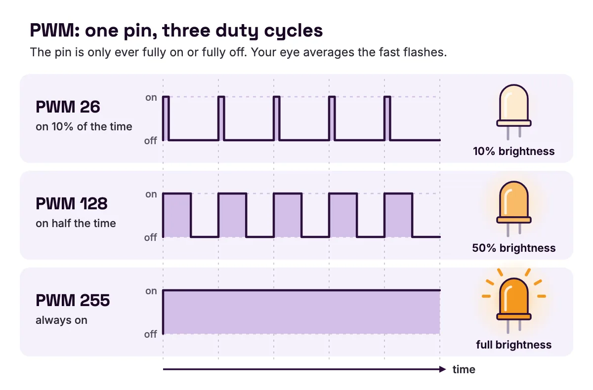
A digital pin is fully on or fully off, so how does an LED dim? With pulse width modulation (PWM): the pin switches on and off very fast, and the share of time it is on is the duty cycle. Arduino's basics of PWM (opens in a new tab) calls this getting analog results with digital means. On its 0 to 255 scale, 255 asks for a 100% duty cycle and 127 for 50%. Your eye averages the fast flashes, so the LED looks dimmer. More in our PWM guide.
On MakerBuddy: the LED Control card's Brightness (PWM) slider runs from 0 to 255. Lesson 4 uses about 26 for 10%, 128 for 50% and 255 for full brightness, the same scale as Arduino's analogWrite (opens in a new tab). On the Potentiometer Mapping card, choose LED PWM and the knob sets the brightness: knob 25 gives about 64, knob 50 about 128 and knob 75 about 191. Each restart sets the mapping back to None on purpose, as the documentation explains.
Idea 12: input, process, output
Every smart device follows one pattern: an input notices, a controller decides and an output acts. Lesson 1 calls the sensors the board's senses, the outputs its muscles and the ESP32 its brain. Lesson 2 gives the simplest case: you press the button, the ESP32 notices, and the buzzer beeps. Our visual guide to the types of sensors covers the input side in depth.
On MakerBuddy you build this pattern without code, as a dashboard rule. A rule watches one or two sensors with >, <, >=, <= or ≈, joined by AND or OR, and runs up to 10 steps. The board holds up to 10 rules and runs them itself, not in your browser, so they keep working after you close the dashboard.
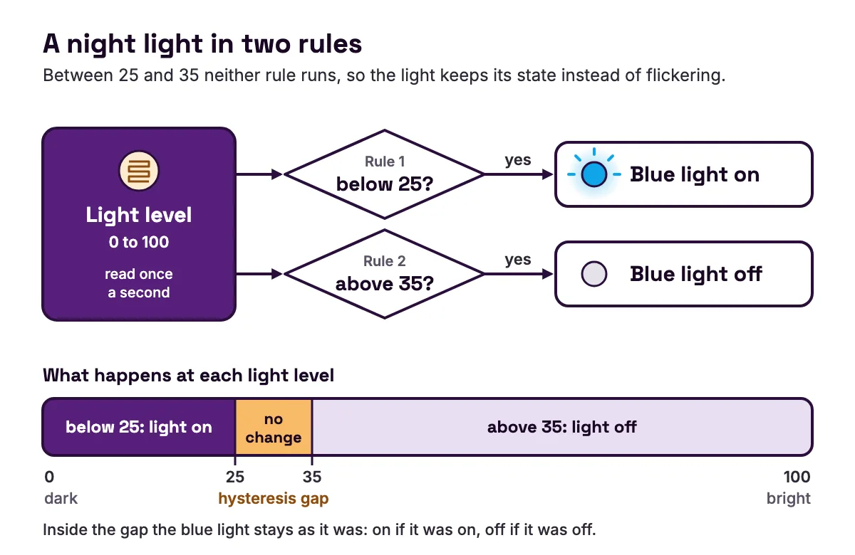
Worked example: a night light in two rules
- 1
Rule 1
Condition mode. Test: light level below 25. Step: blue light on.
- 2
Rule 2
Condition mode. Test: light level above 35. Step: blue light off.
- 3
Test it
cover the light sensor and the blue light comes on within a second or two. Uncover it and the light goes off once the reading passes 35.
Between 25 and 35 neither rule runs, so the light keeps its state instead of flickering. That gap is called hysteresis, and Lesson 7 suggests these two numbers. The board reads its sensors once a second and has no clock, so a rule reacts to readings, never to a time such as "8 pm". Lesson 26 uses the same trick for a fan, with a gap from 26 to 30 °C.
A 45-minute lesson: test all 12 ideas on one board
This plan suits two students sharing a board, or a parent and child. You need USB power, 2.4 GHz Wi-Fi (a phone hotspot works) and Chrome, Edge or Firefox with the free MakerBuddy extension, or Safari on a Mac, iPhone or iPad; Android phones cannot control the board yet. Do the first-time setup in the documentation beforehand. The board's web connection has no password, so use a Wi-Fi network you trust.
| Minutes | Do this | Ideas | Write down |
|---|---|---|---|
| 0–5 | Safety talk; find the six built-in parts without touching them | 12 | Each part: input or output? |
| 5–10 | Plug in the USB cable; open the dashboard | 1, 2 | Voltage in, voltage the chip uses |
| 10–17 | Blue light on and off; slider at 26, 128 and 255 | 3, 9, 11 | How bright each step looks |
| 17–24 | Hold the button for 3 seconds; then try a quick tap | 1, 9 | Which presses showed up |
| 24–32 | Cover the light sensor; then shine a torch on it | 4, 7, 10 | Dark, room and bright readings |
| 32–38 | Map the knob to LED PWM; set it to 25, 50 and 75 | 10, 11 | Predicted vs shown PWM |
| 38–45 | On paper: the LED resistor for 5 V and for 3.3 V | 5, 6, 8 | Resistor, current, power |
- Minutes
- 0–5
- Do this
- Safety talk; find the six built-in parts without touching them
- Ideas
- 12
- Write down
- Each part: input or output?
- Minutes
- 5–10
- Do this
- Plug in the USB cable; open the dashboard
- Ideas
- 1, 2
- Write down
- Voltage in, voltage the chip uses
- Minutes
- 10–17
- Do this
- Blue light on and off; slider at 26, 128 and 255
- Ideas
- 3, 9, 11
- Write down
- How bright each step looks
- Minutes
- 17–24
- Do this
- Hold the button for 3 seconds; then try a quick tap
- Ideas
- 1, 9
- Write down
- Which presses showed up
- Minutes
- 24–32
- Do this
- Cover the light sensor; then shine a torch on it
- Ideas
- 4, 7, 10
- Write down
- Dark, room and bright readings
- Minutes
- 32–38
- Do this
- Map the knob to LED PWM; set it to 25, 50 and 75
- Ideas
- 10, 11
- Write down
- Predicted vs shown PWM
- Minutes
- 38–45
- Do this
- On paper: the LED resistor for 5 V and for 3.3 V
- Ideas
- 5, 6, 8
- Write down
- Resistor, current, power
Expected answers: about 64, 128 and 191 for the knob, and 330 Ω and 150 Ω for the resistors. A good exit question is "An LED needs a resistor, and a light sensor is a resistor. What does each one do?" One limits current; the other turns light into a changing voltage. For a whole year of this, the MakerBuddy curriculum has 32 free lessons of 45 to 60 minutes, written for ages 10 and up.
How to learn electronics: five ways to start, compared
Build first and read second: make something small, notice a question, then look up the theory that answers it. Each way of starting teaches some ideas well and skips others.
| Way to start | What it teaches well | What it misses | Code needed? |
|---|---|---|---|
| Online simulator | Circuits and code with no risk; Wokwi's ESP32 guide (opens in a new tab) lists simulated GPIO, ADC and LEDC PWM | Loose wires, noisy sensors, parts that get warm | Usually |
| Snap-together circuit kit | Loops, switches, series and parallel | Wiring loose parts by hand | No |
| Breadboard and loose parts | Ohm's law, polarity and real wiring | Programming; easy to short the supply | No |
| Arduino-style starter kit | Wiring and code together | Two new skills at once, so a fault could be either | Yes |
| Board with built-in parts and a dashboard | Watching ideas in live readings; rules without code | Hand-wiring, until you add a breadboard | Optional |
- Way to start
- Online simulator
- What it teaches well
- Circuits and code with no risk; Wokwi's ESP32 guide (opens in a new tab) lists simulated GPIO, ADC and LEDC PWM
- What it misses
- Loose wires, noisy sensors, parts that get warm
- Code needed?
- Usually
- Way to start
- Snap-together circuit kit
- What it teaches well
- Loops, switches, series and parallel
- What it misses
- Wiring loose parts by hand
- Code needed?
- No
- Way to start
- Breadboard and loose parts
- What it teaches well
- Ohm's law, polarity and real wiring
- What it misses
- Programming; easy to short the supply
- Code needed?
- No
- Way to start
- Arduino-style starter kit
- What it teaches well
- Wiring and code together
- What it misses
- Two new skills at once, so a fault could be either
- Code needed?
- Yes
- Way to start
- Board with built-in parts and a dashboard
- What it teaches well
- Watching ideas in live readings; rules without code
- What it misses
- Hand-wiring, until you add a breadboard
- Code needed?
- Optional
A sensible path: learn the twelve ideas and watch them happen. Then wire one LED, one resistor and one button on a breadboard and check them with a multimeter. After that, add rules or code and pick a build from our ESP32 and Arduino project ideas for students. Uploading your own Arduino sketch to MakerBuddy replaces its firmware, and the dashboard and rules stop working until you install the firmware again.
The honest case against a board with built-in parts is that it hides the wiring. If you mainly want to solder or design circuits from scratch, start with a breadboard kit. If you would rather see the ideas first and wire later, the MakerBuddy IoT Kit is PKR 40,000 in Pakistan, and schools and families in other countries can ask for a written quote.
Common beginner mistakes, with causes and fixes
Each heading is the symptom you notice.
The LED flashed brightly, then went dark for good
Cause: there was no resistor, so the current shot past the 30 mA limit in the Kingbright datasheet (opens in a new tab). Fix: replace the LED and add a resistor worked out with Ohm's law. For a red LED on 5 V, 330 Ω suits.
The LED stays dark
Cause: the LED is backwards, or the loop is open. Fix: turn the longer leg towards positive, as SparkFun's LED tutorial (opens in a new tab) shows, then trace the loop back to ground.
Your own button circuit reads random values
Cause: a floating input with no pull-up. Fix: add a resistor of about 10 kΩ from the pin to the supply, as SparkFun suggests (opens in a new tab), or switch on the chip's built-in pull-up. MakerBuddy's button already has one.
A 3.3 V pin misbehaves after you fed it 5 V
Cause: the ESP32 datasheet (opens in a new tab) rates its inputs only up to 0.3 V above the 3.3 V supply. Fix: bring the signal down with a voltage divider or a level shifter; see 3.3 V vs 5 V logic.
The multimeter reads 0.00 in current mode
Cause: the meter was set to current and placed across the supply, which SparkFun's multimeter tutorial (opens in a new tab) says blows the meter's fuse. Fix: replace the fuse. Measure voltage across a part, and current in series, in a gap in the loop.
FAQ
What are the basics of electronics?
The basics are circuits, voltage, current and resistance, plus Ohm's law, which links them as V = I × R. Then come power, series and parallel, polarity, digital and analog signals, PWM, and input, process, output. Learn them in that order, because each builds on the last.
How do I start learning electronics as a beginner?
Learn the circuit, voltage, current, resistance and Ohm's law, and watch them happen on real parts. Then wire a simple LED circuit on a breadboard, and add a microcontroller once that works.
Can I learn electronics for free?
Yes. Free tutorials from SparkFun, Arduino and Espressif cover the theory, and Wokwi's free Community plan (opens in a new tab) lets you simulate circuits and code with no parts at all. The 32 lessons in the MakerBuddy curriculum are free too, and more guides like this one are on the MakerBuddy blog.
What are the basic electronic components and their functions?
Resistors limit current, LEDs turn current into light, and buttons open and close a loop. Potentiometers and light-dependent resistors change their resistance, so they work as inputs. Buzzers, motors and relays are outputs, and a microcontroller such as the ESP32 decides in between.
What is the difference between electricity and electronics?
Electricity is the flow of electric charge. Electronics uses that flow on purpose, with parts that switch, sense and control it. Lesson 1 puts it simply: electronics means making electricity do something useful, like lighting a torch.
Is learning electronics safe for a 10-year-old?
Yes, when projects stay at low voltage, such as 5 V USB power, and an adult sets the rules. Never let a child work with mains electricity, and keep relays to low-voltage loads. MakerBuddy's lessons are written for ages 10 and up, with an adult nearby for younger builders.
Do I need a breadboard, multimeter or soldering iron to start?
Not on day one. A simulator, or a board with built-in parts, shows you the ideas first. A breadboard and a multimeter come next, and a soldering iron can wait until you want a circuit to last.
Sources
- SparkFun: Voltage, Current, Resistance, and Ohm's Law (opens in a new tab)
- SparkFun: What is a Circuit? (opens in a new tab)
- SparkFun: Series and Parallel Circuits (opens in a new tab)
- SparkFun: Voltage Dividers (opens in a new tab)
- SparkFun: Electric Power (opens in a new tab)
- SparkFun: Light-Emitting Diodes (LEDs) (opens in a new tab)
- SparkFun: Pull-up Resistors (opens in a new tab)
- SparkFun: Analog vs. Digital (opens in a new tab)
- SparkFun: Alternating Current (AC) vs. Direct Current (DC) (opens in a new tab)
- SparkFun: How to Use a Multimeter (opens in a new tab)
- Kingbright: WP7113ID 5 mm red LED datasheet (opens in a new tab)
- Espressif: ESP32 Series datasheet (opens in a new tab)
- Espressif: Arduino-ESP32 ADC API reference (opens in a new tab)
- Arduino Docs: Basics of PWM (Pulse Width Modulation) (opens in a new tab)
- Arduino Docs: Transistor Motor Control (opens in a new tab)
- Adafruit: Photocells overview (opens in a new tab)
- Wokwi Docs: ESP32 simulation (opens in a new tab)
- Wokwi: Pricing and plans (opens in a new tab)