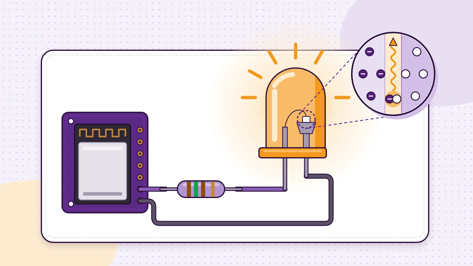
What is a circuit? A circuit is a complete loop that electricity can flow around. It starts at a power source such as a battery, runs through wires and a part that uses the energy, like a bulb, and comes back to the source. Break the loop anywhere and the flow stops.
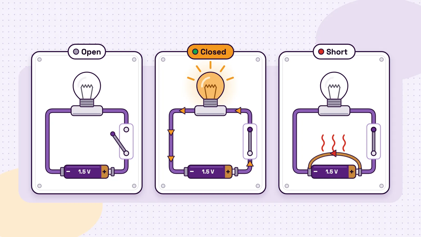
Every circuit is in one of three states. A closed circuit is complete, so current flows and the bulb lights. An open circuit has a gap, so nothing flows. A short circuit is a shortcut that lets the current skip the bulb and rush straight back to the battery, which can make wires and batteries dangerously hot.
Below are labelled diagrams of all three, a comparison table and a worked sum of the current in each. Then you test the idea on a real board, whose push button opens and closes a small circuit every time you press it.
What is a circuit? The simple definition
A circuit is a closed path for electric current. The U.S. Energy Information Administration's guide to batteries, circuits and transformers (opens in a new tab) says that for electricity to flow, it needs a complete path, an electrical circuit. Turning a light on closes the circuit. Turning it off opens it and stops the flow.
Think of a bike chain: cut one link and the wheel stops. Lesson 1 of the MakerBuddy course puts it the same way: a circuit is a complete loop for electricity, and if you break the loop, nothing works.
Two facts are worth knowing early.
- 1
The electrons move slowly, but the effect is instant.
SparkFun's tutorial on what electricity is (opens in a new tab) says that after a second of current, the electrons have moved only fractions of a centimetre, yet the push reaches the whole loop almost at the speed of light. So a bulb lights the moment you close the switch.
- 2
Current is drawn the opposite way to the electrons.
Diagrams show current flowing from positive to negative, a habit that goes back to Benjamin Franklin. SparkFun's guide to what a circuit is (opens in a new tab) explains that electrons really travel the other way. Both arrows describe the same loop.
The circuit is the first of the 12 ideas to know before your first circuit, our beginner's map of basic electronics. For the push behind the flow, read voltage, explained simply. For the flow itself, see electric current, amps and flow. More guides like these are on the MakerBuddy blog.
The four parts of a complete circuit
A simple circuit has four parts. A torch (a flashlight) has all four, and so does the MakerBuddy board.
| Part | Its job | Everyday example | On the MakerBuddy board |
|---|---|---|---|
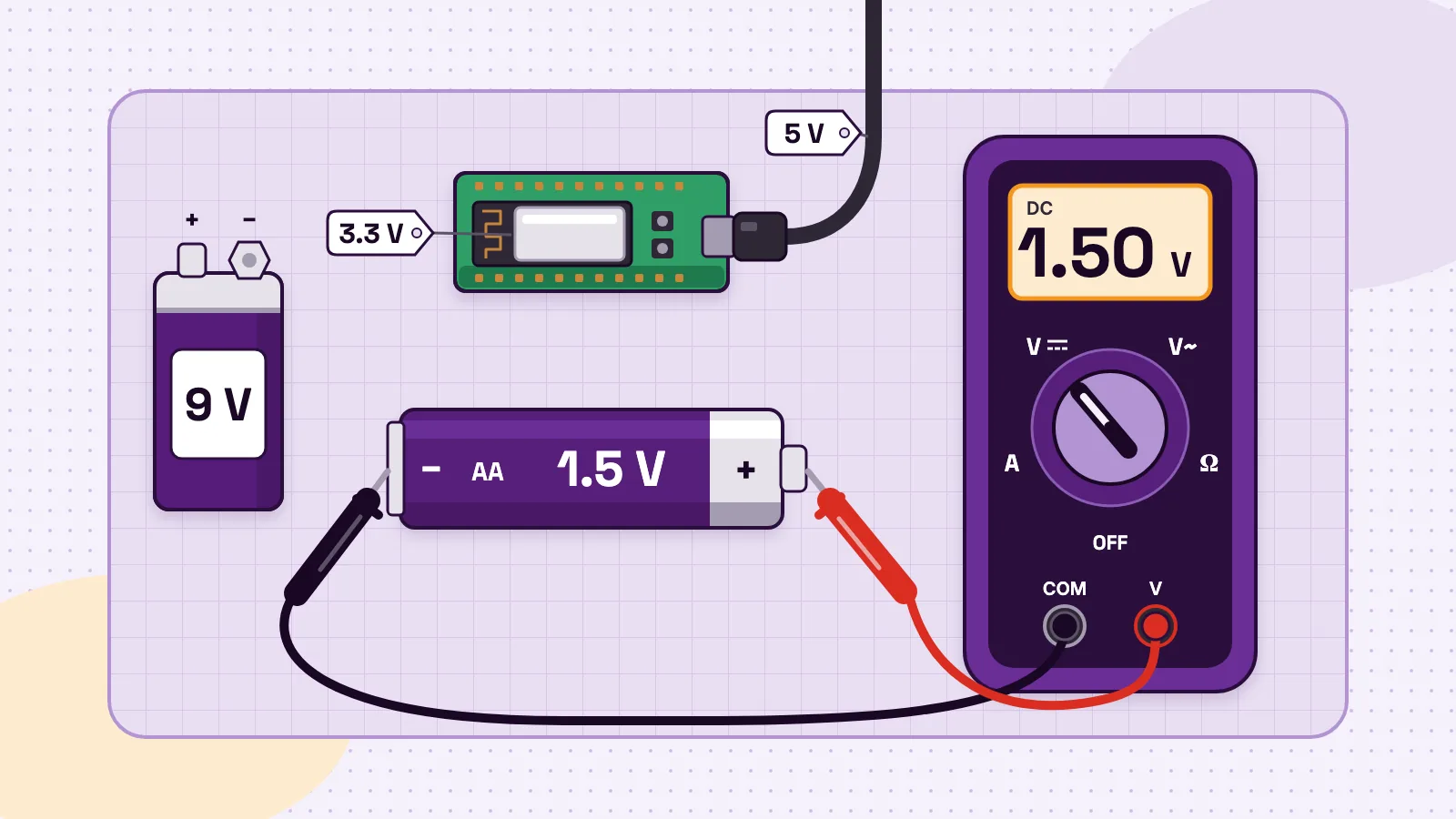
| Power source | Pushes current around the loop; has a positive and a negative side | A battery | 5 V from a USB cable, turned into 3.3 V by the ESP32 DevKit |
| Conductors | Carry the current from part to part | Copper wire | Copper tracks printed on the board |
| Load | Uses the energy to do something | A bulb, an LED, a buzzer | The blue light, the buzzer, the servo |
| Switch | Opens and closes the loop on purpose | A light switch | The built-in push button on pin 5 |
- Part
- Power source
- Its job
- Pushes current around the loop; has a positive and a negative side
- Everyday example
- A battery
- On the MakerBuddy board
- 5 V from a USB cable, turned into 3.3 V by the ESP32 DevKit
- Part
- Conductors
- Its job
- Carry the current from part to part
- Everyday example
- Copper wire
- On the MakerBuddy board
- Copper tracks printed on the board
- Part
- Load
- Its job
- Uses the energy to do something
- Everyday example
- A bulb, an LED, a buzzer
- On the MakerBuddy board
- The blue light, the buzzer, the servo
- Part
- Switch
- Its job
- Opens and closes the loop on purpose
- Everyday example
- A light switch
- On the MakerBuddy board
- The built-in push button on pin 5
Table note: the board's power figures are from the MakerBuddy technical details page.
Conductors and insulators decide where current can go. SparkFun's electricity tutorial (opens in a new tab) names copper, silver and gold as good conductors, and glass, rubber, plastic and air as common insulators. That is why wires are copper inside a plastic coat, and why an open switch works: the gap between its contacts is full of air.
Circuit symbols you will meet
Circuit diagrams, called schematics, use a small drawing for each part. SparkFun's guide to reading a schematic (opens in a new tab) describes the common ones.
| Part | What its symbol looks like |
|---|---|
| Wire | A plain line; a dot where two lines cross means they are joined |
| Battery | Two parallel lines of different lengths; the longer one is positive |
| Switch | Two terminals with a short line between them that does not quite connect |
| Resistor | A zigzag line, or a plain rectangle in international diagrams |
| LED | A triangle pressed against a line, with two small arrows pointing away |
| Ground | One to three flat lines, or a down-pointing triangle |
- Part
- Wire
- What its symbol looks like
- A plain line; a dot where two lines cross means they are joined
- Part
- Battery
- What its symbol looks like
- Two parallel lines of different lengths; the longer one is positive
- Part
- Switch
- What its symbol looks like
- Two terminals with a short line between them that does not quite connect
- Part
- Resistor
- What its symbol looks like
- A zigzag line, or a plain rectangle in international diagrams
- Part
- LED
- What its symbol looks like
- A triangle pressed against a line, with two small arrows pointing away
- Part
- Ground
- What its symbol looks like
- One to three flat lines, or a down-pointing triangle
Open, closed and short circuits: three labelled diagrams
Each diagram shows the same battery, bulb and switch in one loop. Only one thing changes each time.
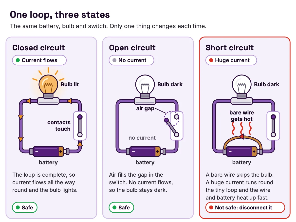
Closed circuit: the loop is complete
- Switch: closed, so its two metal contacts touch.
- Bulb: current flows through it, so it lights.
- The path: one unbroken loop from the battery's positive side back to its negative side.
A closed circuit is also called a complete circuit. It is the normal state of anything switched on, like a lit torch or a doorbell while you press it.
Open circuit: there is a gap
- Switch: open, so air fills the gap between its contacts.
- Bulb: no current reaches it, so it stays dark.
- The path: broken. The current has no way back to the battery.
A gap does not have to be a switch. A loose wire, a half-plugged cable or a snapped lead does the same. SparkFun's circuit guide (opens in a new tab) says that if a circuit you built does not work, an open circuit is the most likely cause.
Short circuit: a shortcut skips the bulb
- Bare wire: joins the battery's two sides with almost no resistance.
- Bulb: the current takes the easy shortcut instead, so the bulb goes dark.
- The path: a tiny loop through the battery and the wire, carrying a huge current.
SparkFun's circuit guide (opens in a new tab) explains that with a wire straight from positive to negative, nothing slows the current down. That can burn up the wire, damage the power supply or drain the battery.
Open vs closed vs short circuits compared
| Closed circuit | Open circuit | Short circuit | |
|---|---|---|---|
| The path | A complete loop through the load | A gap somewhere in the loop | A shortcut that skips the load |
| Current | Flows; the load limits how much | None | Very large |
| The bulb or LED | On | Off | Off |
| Voltage across the gap or switch | Almost none | The battery's full voltage | Almost none |
| Heat | Normal | None | The wire and battery heat up fast |
| Safe? | Yes, with parts rated for the job | Yes | No; disconnect it at once |
| Everyday example | A torch switched on | A torch switched off | A coin touching both ends of a battery |
- The path
- Closed circuit
- A complete loop through the load
- Open circuit
- A gap somewhere in the loop
- Short circuit
- A shortcut that skips the load
- Current
- Closed circuit
- Flows; the load limits how much
- Open circuit
- None
- Short circuit
- Very large
- The bulb or LED
- Closed circuit
- On
- Open circuit
- Off
- Short circuit
- Off
- Voltage across the gap or switch
- Closed circuit
- Almost none
- Open circuit
- The battery's full voltage
- Short circuit
- Almost none
- Heat
- Closed circuit
- Normal
- Open circuit
- None
- Short circuit
- The wire and battery heat up fast
- Safe?
- Closed circuit
- Yes, with parts rated for the job
- Open circuit
- Yes
- Short circuit
- No; disconnect it at once
- Everyday example
- Closed circuit
- A torch switched on
- Open circuit
- A torch switched off
- Short circuit
- A coin touching both ends of a battery
Table note: the open circuit column is why a battery still shows its voltage with nothing connected. Energizer's Alkaline Handbook (opens in a new tab) calls that reading the open circuit voltage, and the reading taken while the battery powers a load the closed circuit voltage.
Watch the trap in the words. An open door lets you through, but an open switch blocks the current. Think of a drawbridge instead: when the bridge is open, nothing can cross.
Open and short circuits are opposites. An open circuit has far too much resistance for current to cross, so nothing flows and nothing gets hurt. A short circuit has almost no resistance, so far too much current flows and things get hot.
Worked example: how much current flows in each circuit
You can work out the current in each state with Ohm's law: current equals voltage divided by resistance, I = V ÷ R. Current is in amps (A), voltage in volts (V) and resistance in ohms (Ω). Our guide to Ohm's law with real examples explains it in full.
The numbers come from Energizer's Alkaline Handbook (opens in a new tab). To test a single cylindrical 1.5 volt alkaline battery, like an AA, Energizer puts it on a load of about 10 Ω, and a fresh battery reads about 1.5 V while it does. Every battery also has a small resistance inside it: about 150 to 300 milliohms, or 0.15 to 0.30 Ω, for fresh Energizer alkaline cylindrical batteries, depending on size.
- 1
Closed circuit.
Treat the 10 Ω test load as the bulb, with 1.5 V across it. I = 1.5 ÷ 10 = 0.15 A, or 150 milliamps (mA). The power is volts times amps: 1.5 × 0.15 = 0.225 watts (W), used by the load.
- 2
Open circuit.
Air fills the gap, so I = 0 A and the power is 0 W. The battery's full voltage sits across the gap.
- 3
Short circuit.
Treat the bare wire's resistance as zero, so only the battery's own resistance is left. I = 1.5 ÷ 0.30 = 5 A, or 1.5 ÷ 0.15 = 10 A. The power is 7.5 to 15 W, almost all of it heat.
| Circuit | Resistance in the loop | Current (I = V ÷ R) | Power |
|---|---|---|---|
| Closed, through a 10 Ω load | About 10 Ω | About 0.15 A (150 mA) | About 0.23 W, used by the load |
| Open, an air gap | Too high for current to cross | 0 A | 0 W |
| Short, a bare wire | 0.15 to 0.30 Ω, inside the battery | 5 to 10 A | 7.5 to 15 W, nearly all as heat |
- Circuit
- Closed, through a 10 Ω load
- Resistance in the loop
- About 10 Ω
- Current (I = V ÷ R)
- About 0.15 A (150 mA)
- Power
- About 0.23 W, used by the load
- Circuit
- Open, an air gap
- Resistance in the loop
- Too high for current to cross
- Current (I = V ÷ R)
- 0 A
- Power
- 0 W
- Circuit
- Short, a bare wire
- Resistance in the loop
- 0.15 to 0.30 Ω, inside the battery
- Current (I = V ÷ R)
- 5 to 10 A
- Power
- 7.5 to 15 W, nearly all as heat
Table note: the 1.5 V battery, the 10 Ω test load and the 150 to 300 milliohm internal resistance are from Energizer's Alkaline Handbook (opens in a new tab). The wire's resistance is treated as zero.
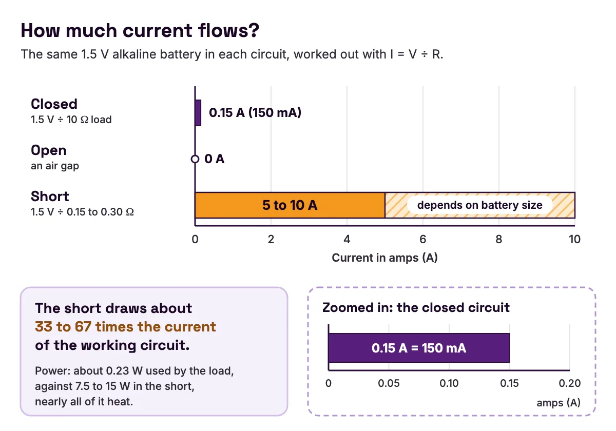
So the short draws about 33 to 67 times the current of the working circuit, from the same small battery. Treat these as estimates: a real battery's voltage sags under a heavy load, and its resistance changes as it heats. Energizer's own short test, called flash amps, lasts only about 0.2 seconds, as the handbook (opens in a new tab) describes.
Why short circuits are dangerous, and what stops them
In a short circuit nothing does useful work, so the energy has one place to go: heat. A thin wire can glow, its plastic coat can melt and the battery can get too hot to hold. Energizer's Alkaline Handbook (opens in a new tab) adds that short circuits may make a battery leak, and warns against carrying loose batteries with coins or paper clips: one piece of metal across both ends makes a short and can generate high heat.
The defence is a deliberate weak point. A fuse is a thin wire built to melt first, which opens the circuit before anything else is harmed; a circuit breaker does the same job with a switch that trips off. Even a multimeter has one. SparkFun's multimeter tutorial (opens in a new tab) explains that probing across a supply in current mode shorts it through the meter, and the meter's 200 mA fuse burns out. A fuse turns a dangerous short circuit into a safe open circuit.
How a switch opens and closes a circuit
A switch is a gap you control. Inside, two metal contacts either touch, closing the circuit, or sit apart, opening it.
| Switch | How it behaves | Where you meet it |
|---|---|---|
| Push button | Closed only while you press it; a spring opens it again | Doorbells, keyboards, the MakerBuddy button |
| Toggle or rocker | Stays where you leave it | Light switches |
| Slide | Stays where you leave it | Torches, toys |
| Relay | An electromagnet moves the contacts, so a small signal switches a separate circuit | A small low-voltage load switched by a microcontroller, as in Lesson 15 |
| Transistor | No moving parts; a small current controls a larger one | Motor drivers, and inside microchips |
- Switch
- Push button
- How it behaves
- Closed only while you press it; a spring opens it again
- Where you meet it
- Doorbells, keyboards, the MakerBuddy button
- Switch
- Toggle or rocker
- How it behaves
- Stays where you leave it
- Where you meet it
- Light switches
- Switch
- Slide
- How it behaves
- Stays where you leave it
- Where you meet it
- Torches, toys
- Switch
- Relay
- How it behaves
- An electromagnet moves the contacts, so a small signal switches a separate circuit
- Where you meet it
- A small low-voltage load switched by a microcontroller, as in Lesson 15
- Switch
- Transistor
- How it behaves
- No moving parts; a small current controls a larger one
- Where you meet it
- Motor drivers, and inside microchips
Switches also have a resting state. A normally open switch stays open until you press it, like the MakerBuddy button; a normally closed switch stays closed until you press it. To tell them apart, unplug the power and test the switch with a multimeter on continuity: a beep at rest means normally closed.
The kit's relay has both kinds of contact: Lesson 15 shows its COM terminal joined to NC (normally closed) when it is off and to NO (normally open) when it is on. Our guide to how a relay lets a small signal switch a big load explains more. For the switch with no moving parts, read what a transistor is.
The MakerBuddy push button: a circuit you can watch
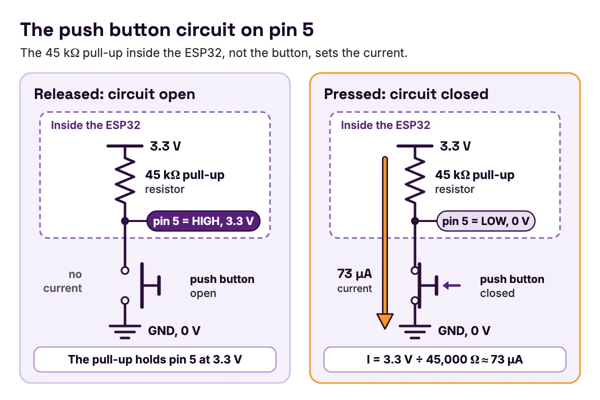
The MakerBuddy board has a push button built in, wired to pin 5 of the ESP32, so there is nothing to wire. Lesson 6 explains the circuit behind it. Inside the ESP32, pin 5 is joined to 3.3 V through a resistor called a pull-up. The button sits between pin 5 and GND, which is 0 V.
- Released: the button is an open switch. No current flows through it, so the pull-up holds pin 5 at 3.3 V and the pin reads HIGH.
- Pressed: the button closes the circuit. Current flows from 3.3 V through the pull-up and the button to ground, so pin 5 drops to 0 V and reads LOW.
MakerBuddy flips this for you, so the dashboard's Push Button card says Pressed when the pin is LOW.
Worked check: is pressing the button a short circuit?
Pressing joins pin 5 to ground with bare metal contacts, which sounds like a short. It is not, because the pull-up resistor sits in the same loop. The ESP32 datasheet (opens in a new tab) gives the internal pull-up a typical resistance of 45 kΩ, which is 45,000 Ω.
- 1
Voltage across the loop
3.3 V.
- 2
Resistance in the loop
45,000 Ω. The closed button adds almost nothing.
- 3
Current
I = 3.3 ÷ 45,000 = 0.000073 A, or about 73 microamps (µA).
- 4
Check
the datasheet gives the pull-up's drive strength as about 75 µA. The sum agrees.
That is at least 68,000 times less than the 5 to 10 A of the battery short. One resistor turns a would-be short into a safe closed circuit. Our guide to pull-up and pull-down resistors goes further, and how LEDs work and why they need a resistor shows the same idea protecting an LED.
Watch the circuit open and close
You need the board, a USB cable and power, 2.4 GHz Wi-Fi, and a laptop with the Chrome, Edge or Firefox extension, or Safari on a Mac, iPhone or iPad. Android phones cannot control the board yet. Do the first-time setup beforehand. The board's local connection has no password, so use a Wi-Fi network you trust and never open it to the internet, as the school network notes explain.
- 1
Connect the dashboard and find the Push Button card. It says Released: the circuit is open.
- 2
Hold the button for about 3 seconds. The card changes to Pressed: the circuit is closed.
- 3
Let go. The card returns to Released, which can take up to 2 seconds.
- 4
Try a quick tap. Predict first, then watch.
Some taps never show. Lesson 6 explains why: the board checks the button once a second, and the dashboard gets a new reading about every 2 seconds. A quick tap can close and open the circuit between two checks.
The ESP32 DevKit has two more small buttons, BOOT and EN, which Espressif's esptool troubleshooting guide (opens in a new tab) uses to start upload mode, so leave them alone. Need a board? You can order the MakerBuddy IoT Kit for a class or for home.
Common circuit mistakes: symptom, cause and fix
Nothing happens when you close the switch
Symptom: the switch is on, but the bulb or LED stays dark. Cause: an open circuit somewhere else in the loop: a loose wire, a half-plugged cable, a broken lead or a flat battery. An LED fitted backwards blocks the current too. Fix: unplug the power and trace the loop from positive, through every part, back to negative. A multimeter's continuity test finds the gap, and our beginner's guide to using a multimeter walks you through it.
A wire or battery gets hot
Symptom: a wire feels warm, smells of hot plastic, or the battery gets hot. Cause: a short circuit: a bare wire, a screwdriver tip or a coin joining the two sides of the supply. Fix: disconnect the power at once, without grabbing a hot battery, and find the shortcut before you power up again. Do not replace a blown fuse until you know what blew it.
You set the button's pin as an output
Symptom: in your own sketch, pin 5 misbehaves or stops working after a press. Cause: the pin was set to OUTPUT and driven HIGH, so pressing the button joins a pin pushing 3.3 V straight to ground: a short through the pin. Arduino's digital pins guide (opens in a new tab) warns, for its own boards, that short circuits on pins can damage the pin or the whole chip. Fix: a button's pin is always an input. Use INPUT_PULLUP.
FAQ
What is a circuit in simple terms?
A circuit is a loop that electricity travels around. It leaves a power source, passes through wires and a part that uses the energy, like a bulb or a buzzer, and returns to the source. If the loop is complete, the part works. If it is broken anywhere, it does not.
What is the purpose of a circuit?
A circuit carries energy from a source to something that does a job, such as lighting a bulb or turning a motor, and its switches decide when. In a board like the ESP32, circuits also carry signals, such as a button telling the chip it has been pressed.
How do you explain a circuit to a child?
Use a toy train on a round track. The battery is the station, the track is the wire and the train is the electricity. If one piece of track is missing, the train cannot get round, and that is an open circuit.
What is the difference between an open and a closed circuit?
A closed circuit is a complete loop, so current flows and the device works. An open circuit has a gap, such as an open switch or a broken wire, so no current flows. Think of a drawbridge: when it is open, nothing crosses.
What opens and closes an electrical circuit?
A switch. Inside, two metal contacts touch to close the circuit or move apart to open it. Push buttons, light switches and relays are all switches, and a transistor does the same job with no moving parts.
Is a broken wire an open circuit?
Yes. A break anywhere in the loop is an open circuit, whether it is an open switch, a snapped wire, a loose plug or a blown fuse. SparkFun's circuit guide (opens in a new tab) names a broken connection or a loose wire as the usual reason a circuit is open.
How do you test if a circuit is open or closed?
Turn the power off, set a multimeter to continuity mode and touch the probes to both ends of the path. SparkFun's multimeter tutorial (opens in a new tab) explains that the meter sounds a tone when the resistance between the probes is very low. A tone means closed; silence means there is a gap between the probes.
What happens if a circuit is short-circuited?
The current skips the load and becomes very large, so the wire and the power source heat up fast. SparkFun's circuit guide (opens in a new tab) warns this can burn the wire, damage the supply or drain the battery. A short does not fix itself: it stops only when something breaks the loop, such as a fuse blowing. Disconnect the power and find the cause.
What are the five types of circuits?
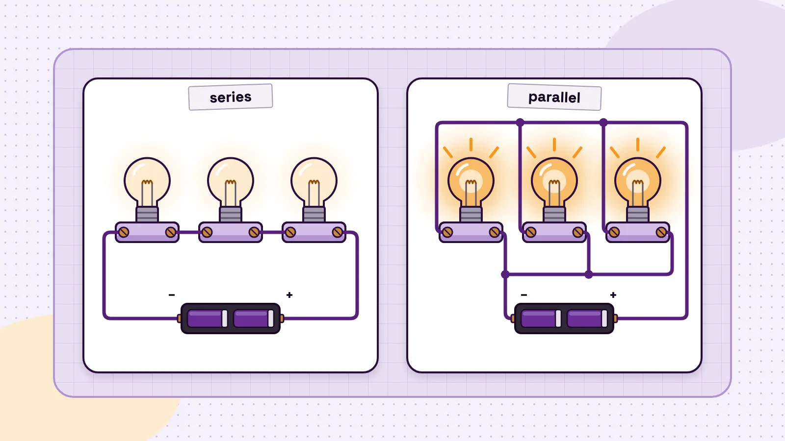
There is no single official list. Five names you will meet early are closed, open and short circuits, which describe the state of a loop, and series and parallel circuits, which describe how the parts are arranged. SparkFun's series and parallel tutorial (opens in a new tab) explains that series parts share one path, and our guide to series vs parallel circuits compares the two.
Sources
- U.S. Energy Information Administration: Batteries, circuits, and transformers (opens in a new tab)
- SparkFun: What is a Circuit? (opens in a new tab)
- SparkFun: What is Electricity? (opens in a new tab)
- SparkFun: How to Read a Schematic (opens in a new tab)
- SparkFun: Series and Parallel Circuits (opens in a new tab)
- SparkFun: How to Use a Multimeter (opens in a new tab)
- Energizer: Alkaline Manganese Dioxide Handbook and Application Manual (opens in a new tab)
- Espressif: ESP32 Series datasheet (opens in a new tab)
- Espressif: Arduino-ESP32 GPIO API reference (opens in a new tab)
- Espressif: esptool troubleshooting for the ESP32 (opens in a new tab)
- Arduino Docs: Digital Pins (opens in a new tab)
- Arduino Docs: Debounce on a Pushbutton (opens in a new tab)