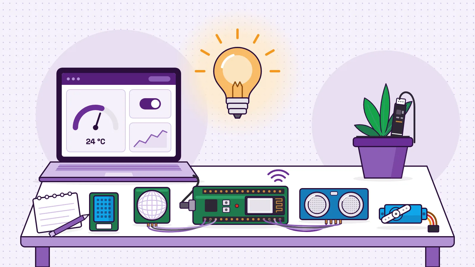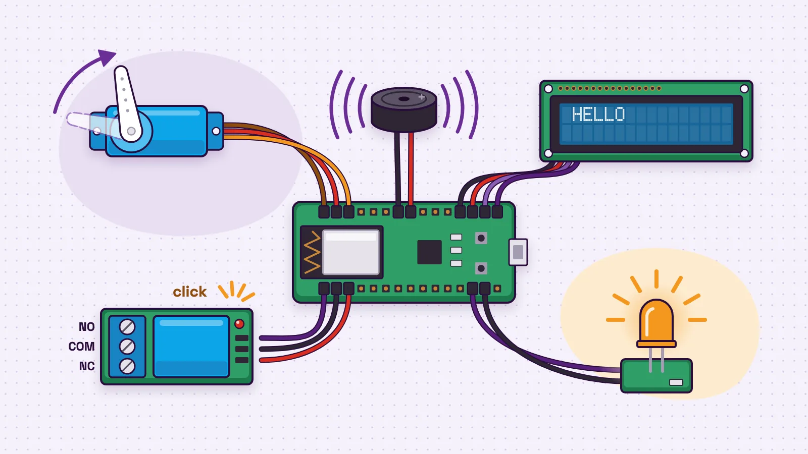
What is an actuator? An actuator is a device that turns a control signal into physical action. It takes energy, usually electricity, compressed air or pressurised liquid, and uses it to move, push, turn or switch something. In student electronics, the actuators a microcontroller controls are motors, servos and relays, alongside output devices like buzzers, lights and screens.
A sensor tells a project what is happening. An actuator lets the project do something about it. A temperature sensor notices a hot room, and a fan turns on. A distance sensor sees a toy car, and a gate lifts. Our visual guide to the types of sensors covers the input side. This post covers the output side.
First you will see how actuators work and the main types engineers use. Then we walk through every output on the MakerBuddy kit: the built-in blue LED, colour LED and buzzer, and the plug-in servo, relay and text screen. For each one you get what it does, how the board controls it, the lesson that teaches it and the mistakes students make most. There is also a short Arduino sketch you can upload.
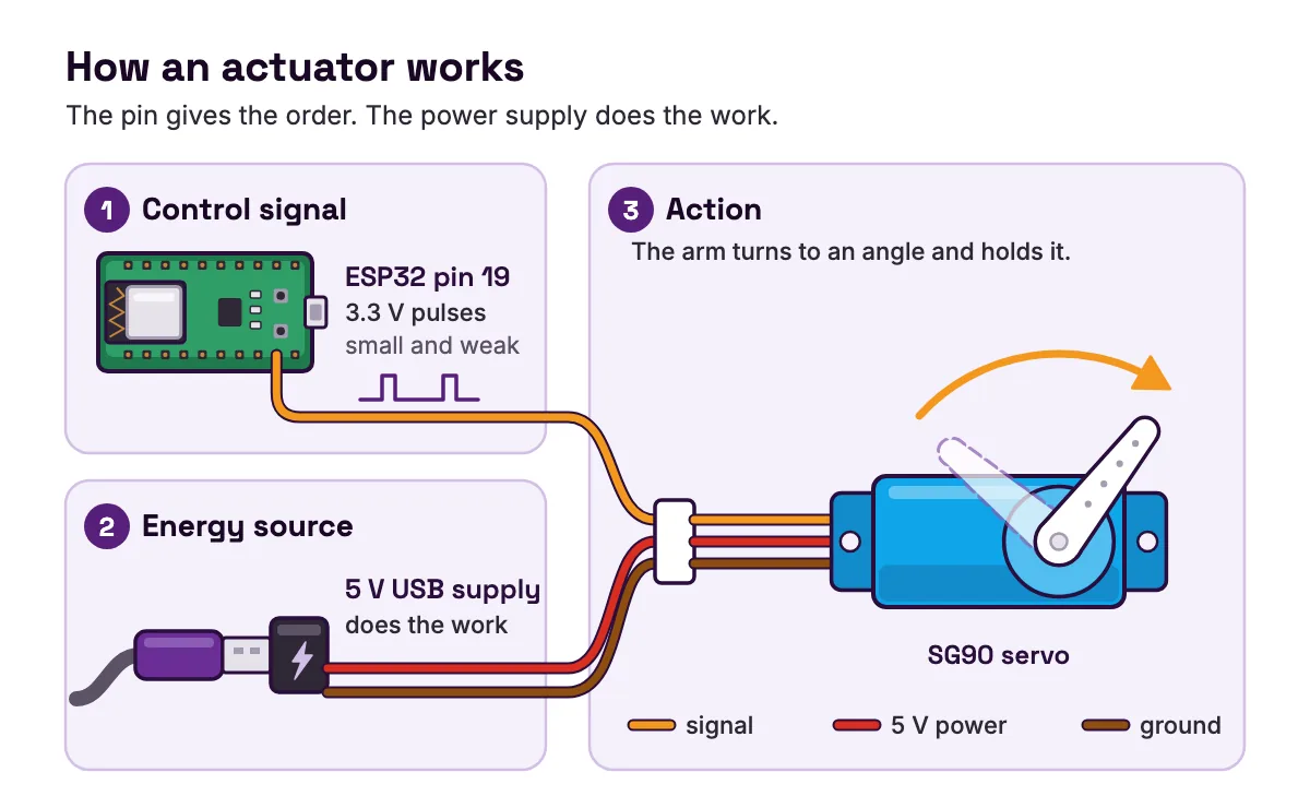
How an actuator works: signal, energy, action
Every actuator has three things going on at once.
- 1
A control signal.
This is the instruction. It is small and weak, like a microcontroller pin switching to 3.3 V to say "on".
- 2
An energy source.
This is what does the work. It might be a 5 V USB supply, a battery, an air compressor or a hydraulic pump.
- 3
The action.
The energy becomes motion, sound, light or a switched circuit.
The clever part is that the signal and the energy are kept apart. Arduino's guide to its relay shield (opens in a new tab) explains that relays let a low-power microcontroller control circuits that need far more power than the board can handle directly. Its guide to motor control with a transistor (opens in a new tab) makes the same point for motors: most motors need more current or voltage than a pin can give, so a transistor does the heavy switching while the pin only gives the order.
So a microcontroller rarely powers an actuator straight from its pin. The pin decides. Something else delivers the energy. A small LED is the exception, because it needs so little current that a pin can light it directly.
Actuators also differ in the kind of motion they make. The actuator maker LINAK sorts them in its guide to what an actuator is (opens in a new tab) into linear and rotary. A linear actuator moves something in a straight line, like lifting a desk up and down. A rotary actuator turns something around an axis, like opening a valve, a door or a gate. The servo in a school kit is a small rotary actuator.
Types of actuators compared
Engineers usually sort actuators by the energy they use. The table below follows the five families in LINAK's actuator guide (opens in a new tab), then adds one column that matters to students: will you meet it on a classroom desk?
| Type | Energy it uses | What it is good at | Where you find it | In a student electronics kit? |
|---|---|---|---|---|
| Electric | Electricity, through motors or solenoids | Precise control of motion; clean and simple to maintain | Robotics, automation, electronics | Yes. Servos, DC motors and relays are all electric |
| Hydraulic | Pressurised liquid, usually oil | Very high force | Construction equipment, heavy machinery, industrial presses | Rarely. It needs a pump and sealed fluid that must be checked |
| Pneumatic | Compressed air | Fast movement and simple control for lighter loads | Machines that make quick moves with light loads | Rarely. It needs an air supply and tubing |
| Piezoelectric | An electric field | Very precise positioning | Precise positioning tools | Not as a motion part |
| Thermal | Heat | Changing shape when warmed | Shape memory alloy parts | No |
- Type
- Electric
- Energy it uses
- Electricity, through motors or solenoids
- What it is good at
- Precise control of motion; clean and simple to maintain
- Where you find it
- Robotics, automation, electronics
- In a student electronics kit?
- Yes. Servos, DC motors and relays are all electric
- Type
- Hydraulic
- Energy it uses
- Pressurised liquid, usually oil
- What it is good at
- Very high force
- Where you find it
- Construction equipment, heavy machinery, industrial presses
- In a student electronics kit?
- Rarely. It needs a pump and sealed fluid that must be checked
- Type
- Pneumatic
- Energy it uses
- Compressed air
- What it is good at
- Fast movement and simple control for lighter loads
- Where you find it
- Machines that make quick moves with light loads
- In a student electronics kit?
- Rarely. It needs an air supply and tubing
- Type
- Piezoelectric
- Energy it uses
- An electric field
- What it is good at
- Very precise positioning
- Where you find it
- Precise positioning tools
- In a student electronics kit?
- Not as a motion part
- Type
- Thermal
- Energy it uses
- Heat
- What it is good at
- Changing shape when warmed
- Where you find it
- Shape memory alloy parts
- In a student electronics kit?
- No
LINAK's guide also names the trade-offs. Electric actuators give precise control but usually cannot match hydraulic force. Hydraulic actuators are strong but need their fluid contained and maintained. Pneumatic ones are quick and simple but suit lighter loads.
For a student, the choice is easy. Electric actuators run from the same USB power as the board, and you control them with the same pins that read your sensors. That is why every actuator in this post is electric.
Actuators vs output devices: where LEDs, buzzers and screens fit
Here is an honest wrinkle. In the strict engineering sense, an actuator makes something move. A servo turns. A motor spins. A relay moves a small metal arm inside its case. By that rule, an LED or a text screen is not an actuator, because nothing moves.
Teachers and textbooks often use a wider word: output devices. An output device is anything a controller uses to act on the world, whether by moving, lighting up, making a sound or showing words. The MakerBuddy lessons use this idea from the start, with Input, Process, Output as the core model, and Lesson 8 reviews it with the LEDs and the buzzer.
| Part | Does something move? | Strict actuator? | Output device? |
|---|---|---|---|
| Servo | Yes, the shaft turns to an angle | Yes | Yes |
| DC motor | Yes, the shaft spins | Yes | Yes |
| Relay | Yes, a metal arm flips the contacts | Yes | Yes |
| Buzzer | A thin disc vibrates to push the air | Borderline | Yes |
| LED | No, it gives light | No | Yes |
| LCD screen | No, it shows characters | No | Yes |
- Part
- Servo
- Does something move?
- Yes, the shaft turns to an angle
- Strict actuator?
- Yes
- Output device?
- Yes
- Part
- DC motor
- Does something move?
- Yes, the shaft spins
- Strict actuator?
- Yes
- Output device?
- Yes
- Part
- Relay
- Does something move?
- Yes, a metal arm flips the contacts
- Strict actuator?
- Yes
- Output device?
- Yes
- Part
- Buzzer
- Does something move?
- A thin disc vibrates to push the air
- Strict actuator?
- Borderline
- Output device?
- Yes
- Part
- LED
- Does something move?
- No, it gives light
- Strict actuator?
- No
- Output device?
- Yes
- Part
- LCD screen
- Does something move?
- No, it shows characters
- Strict actuator?
- No
- Output device?
- Yes
Does the label matter? For a test answer, yes, so check which definition your teacher uses. For building, not really. You control all of them the same way: with a signal that says on, off, how much, or what to show.
The MakerBuddy kit's outputs at a glance
MakerBuddy is a learning board built around an ESP32, a small computer with Wi-Fi. According to the technical details, every kit has 6 parts built into the board and 9 that plug into labelled sockets. Six of those parts are outputs. The table shows each one, the pin it uses and the lesson that teaches it.
| Output | Built in or plug-in | What it does | Pin (GPIO) | How the board controls it | Lesson |
|---|---|---|---|---|---|
| Blue LED | Built in | Lights up and dims | 12 | Digital on/off, plus PWM brightness from 0 to 255 | Lesson 4 |
| Colour LED (RGB) | Built in | Mixes red, green and blue light | 13, 14 and 27 | PWM on three channels, each 0 to 255 | Lesson 5 |
| Buzzer | Built in | Sounds one tone | 4 | Digital on/off; the dashboard button beeps for 500 ms | Lesson 8 |
| SG90 servo | Plug-in | Turns to an angle from 0 to 180° | 19 | PWM pulses at 50 Hz, 500 to 2500 µs wide | Lesson 14 |
| Relay | Plug-in | Switches a small low-voltage fan or bulb | 23 | Digital on/off, switched at once | Lesson 15 |
| 1602 LCD | Plug-in | Shows 2 lines of 16 characters | SDA 21, SCL 22 | I2C messages to address 0x27 | Lesson 19 |
- Output
- Blue LED
- Built in or plug-in
- Built in
- What it does
- Lights up and dims
- Pin (GPIO)
- 12
- How the board controls it
- Digital on/off, plus PWM brightness from 0 to 255
- Lesson
- Lesson 4
- Output
- Colour LED (RGB)
- Built in or plug-in
- Built in
- What it does
- Mixes red, green and blue light
- Pin (GPIO)
- 13, 14 and 27
- How the board controls it
- PWM on three channels, each 0 to 255
- Lesson
- Lesson 5
- Output
- Buzzer
- Built in or plug-in
- Built in
- What it does
- Sounds one tone
- Pin (GPIO)
- 4
- How the board controls it
- Digital on/off; the dashboard button beeps for 500 ms
- Lesson
- Lesson 8
- Output
- SG90 servo
- Built in or plug-in
- Plug-in
- What it does
- Turns to an angle from 0 to 180°
- Pin (GPIO)
- 19
- How the board controls it
- PWM pulses at 50 Hz, 500 to 2500 µs wide
- Lesson
- Lesson 14
- Output
- Relay
- Built in or plug-in
- Plug-in
- What it does
- Switches a small low-voltage fan or bulb
- Pin (GPIO)
- 23
- How the board controls it
- Digital on/off, switched at once
- Lesson
- Lesson 15
- Output
- 1602 LCD
- Built in or plug-in
- Plug-in
- What it does
- Shows 2 lines of 16 characters
- Pin (GPIO)
- SDA 21, SCL 22
- How the board controls it
- I2C messages to address 0x27
- Lesson
- Lesson 19
The board comes in purple or green. Both colours are the same MakerBuddy IoT Kit V1.0 board, so everything here applies to either one.
The MakerBuddy kit's box list shows every part with the lesson that teaches it. The kit photo there also shows a small motor with a fan blade and a small bulb. Ask us which of these come with your order.
Light and sound: the blue LED, colour LED and buzzer
These three outputs are soldered onto the board, so they need no wiring. They are the first outputs that the 32 free lessons in the MakerBuddy curriculum use.
The blue LED
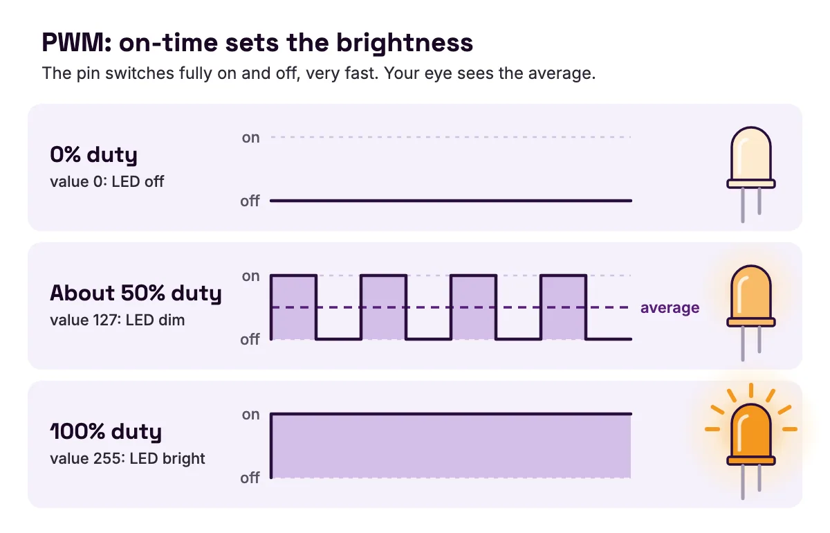
An LED lets current flow through it in only one direction, and gives light when it does. On MakerBuddy the blue LED sits on GPIO 12. The dashboard has an LED On/Off switch and a Brightness (PWM) slider that runs from 0 to 255. The slider only works while the LED is switched on. Lesson 4 teaches both.
Brightness comes from a trick called PWM, or pulse width modulation. Arduino's basics of PWM (opens in a new tab) calls it "a technique for getting analog results with digital means." The pin switches fully on and fully off very fast. The share of time it spends on is the duty cycle. In Arduino's analogWrite, a value of 255 is a 100% duty cycle and 127 is about 50%. Your eye cannot see the flicker, so it sees the average, and the LED looks dimmer.
The colour LED
The colour LED holds three tiny lights, red, green and blue, in one package. Each one gets its own brightness from 0 to 255, and your eye blends them into one colour. All three at full look white. Lesson 5 has students mix teal and orange with the three sliders.
There is one detail to know if you ever write your own code. The MakerBuddy firmware drives the colour LED on GPIO 13, 14 and 27 as a common-anode LED. That means it writes 255 minus the value you ask for. A raw analogWrite(13, 0) turns red fully on, not off. Rules can set the colour LED to seven ready-made colours or off: red, green, blue, yellow, purple, cyan and white.
The buzzer
The buzzer sits on GPIO 4. It is on or off, with one tone. It cannot play different notes.
The buzzer maker Same Sky (formerly CUI Devices) explains why in its guide to buzzer technologies and drive circuits (opens in a new tab). Some buzzers, which it calls indicators, have their driving circuit built in, so a plain on signal makes them sound, but only at their one fixed frequency. Others, called transducers, have no driver, and you must send them a square wave to set the pitch. MakerBuddy's buzzer behaves like an indicator: switch it on and it beeps.
On the dashboard, the Activate Buzzer button gives one half-second beep. Inside a rule, a buzzer_on step keeps the buzzer sounding until a buzzer_off step. Lesson 8 uses the buzzer for a traffic light, and Lesson 28 uses it in a gas alarm model. That gas build is for learning only. Never use it as a real gas or smoke alarm.
Motion: the SG90 servo and the small DC motor
Motors are what most people picture when they hear the word actuator. The kit's servo turns to an exact angle and holds it. A plain DC motor spins for as long as it has power.
The SG90 servo
A servo is a small motor, a gearbox, a position sensor and a control circuit in one box. The controller keeps sending the angle it wants. The servo turns until its shaft matches, then stops and holds. This checking loop is called closed-loop control. If something nudges the horn, the servo pushes back. Lesson 14 explains it with a cardboard parking barrier.
The angle is set by the width of a pulse. The SG90 data sheet (opens in a new tab) draws a pulse every 20 ms (50 Hz). A 1.5 ms pulse puts the horn in the middle, about 1 ms turns it fully one way and about 2 ms fully the other. The same sheet lists an operating voltage of 4.8 V (about 5 V), a stall torque of 1.8 kgf·cm and roughly 180 degrees of travel. Its three wires are orange for the pulse signal, red for power and brown for ground. A torque of 1.8 kgf·cm means the servo can hold about 1.8 kg pulling 1 cm from the shaft. At 2 cm it can only hold half that, so long, heavy arms are a problem.
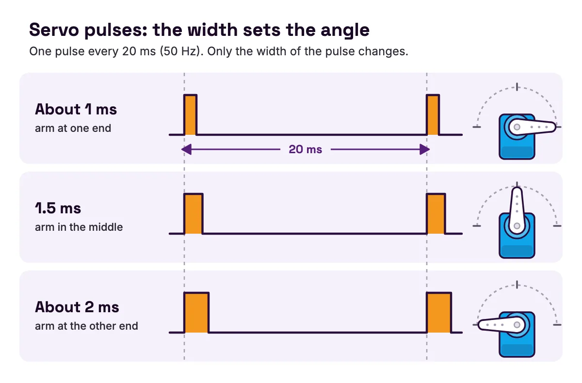
MakerBuddy plugs the servo into the socket marked 19. The firmware sends 50 Hz pulses with 16-bit precision and maps 0 to 180° onto pulses from 500 to 2500 µs. That is wider than the 1 to 2 ms drawn on the data sheet, and every SG90 is a little different. So the best working angles for your servo may not be exactly 0° and 180°. Lesson 14 has you find your servo's real limits and keep your angles a little inside them.
You can move the servo four ways: the dashboard slider, the knob on the board, a sensor such as soil moisture or light, or a rule. The servo control notes explain that only one of them controls the servo at a time. While a rule, the knob or a sensor holds it, the board refuses slider commands. The servo keeps holding its last angle, but it cannot report where it really is. The parking gate project in Lesson 29 builds on all of this.
The small DC motor and fan
A DC motor spins nonstop while powered and does not know its position. Arduino's motor control guide (opens in a new tab) explains how. Current through a coil of wire makes a magnetic field. Magnets inside the motor's body push and pull on that field, and the shaft turns. The same guide warns that motors pull the most current when they start or carry a load, and suggests a diode across the motor's leads to soak up the small current the spinning shaft makes when it stops.
To change a DC motor's speed, you send PWM to a transistor or motor driver, not straight to the motor. The higher the PWM value, the faster it spins.
MakerBuddy does not drive the fan from a PWM pin. It switches the fan on and off through the relay, which you will meet next. So a small fan wired through the relay runs at one speed: on or off. In Lesson 26, students build a smart fan rule that turns the relay on when the temperature goes above 30 °C, and a bonus rule turns it off again below 26 °C. The gap between the two numbers stops the fan flicking on and off.
Switching power: how the relay works
A relay is a switch flipped by an electromagnet. Arduino's relay shield guide (opens in a new tab) describes it as an electromagnet that moves a small metal arm, the COM terminal, between two positions: NC (normally closed) and NO (normally open). It also points out that controlling a relay in code works much like turning an LED on or off.
Here is what happens on the kit, step by step, as Lesson 15 explains it.
- 1
The ESP32 sets GPIO 23 to 3.3 V.
- 2
A small transistor on the relay module switches on.
- 3
Current from the board's 5 V supply flows through the relay's coil.
- 4
The coil becomes a magnet and pulls the metal arm. You hear a click, and the module's indicator LED lights.
- 5
COM disconnects from NC and connects to NO, which completes the separate load circuit.
- 6
When the pin goes back to 0 V, a spring pulls the arm back with a second click.
Only magnetism links the two sides. This is called galvanic isolation. The circuit you switch has no electrical connection to the ESP32.
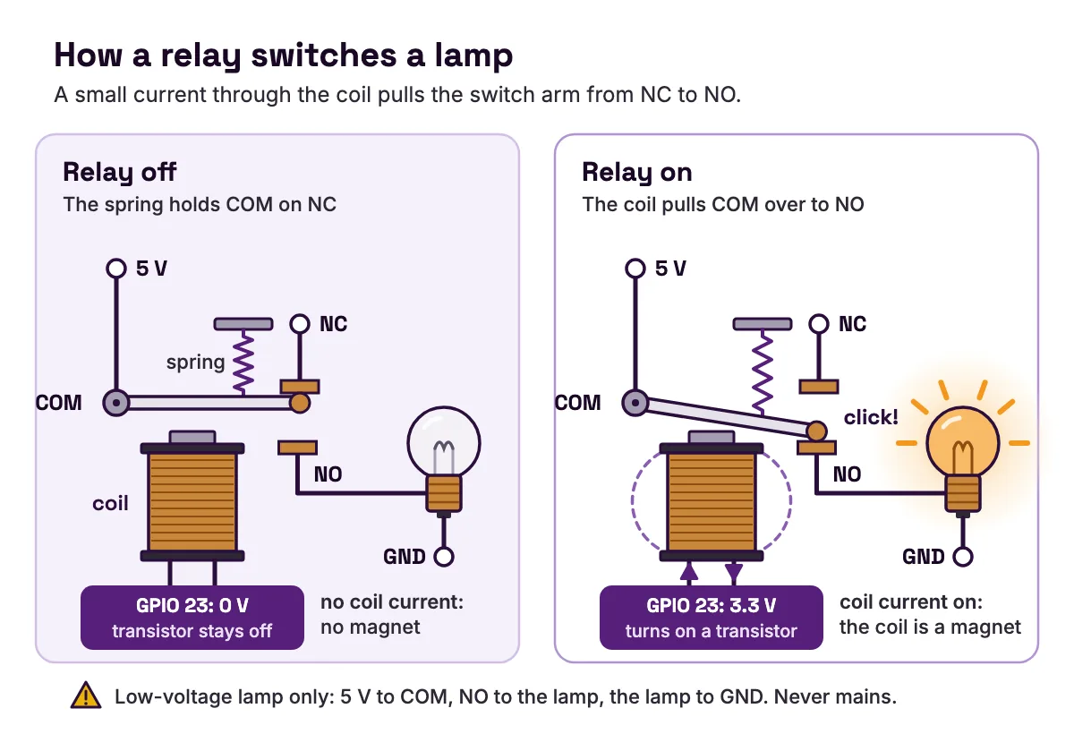
In the lesson, students wire the load with their teacher and with the USB cable unplugged: the board's 5V plug to COM, NO to the bulb or fan, and the bulb or fan's other lead to GND. The load stays off until the relay switches on. The firmware switches the relay at once. The REST API documentation notes that it ignores the delay fields some older apps send.
Why use a relay rather than a transistor? Lesson 15 gives the trade-off. A relay fully isolates the two circuits and can carry larger currents. But it switches more slowly, wears out over time and clicks. Its contacts can even weld shut, which leaves the load on.
Text: the 1602 LCD screen
The text screen shows 2 lines of 16 characters. It is called a 1602 for exactly that reason. It shows letters, numbers and symbols, not pictures. Lesson 19 turns it into an electronic billboard.
The screen talks to the board over I2C. I2C needs only two signal wires, SDA for data and SCL for the clock, plus two for power. On MakerBuddy those are GPIO 21 and 22, and the board talks to the screen at address 0x27. Several I2C parts can share the same two wires because each one has its own address.
The screen has two modes. By default it cycles through sensor screens. In custom mode it shows your own two lines, redrawn every 5 seconds. Your lines can include live readings with ten wildcards, such as {temp}, {humidity} and {distance}. The LCD screen notes explain the catch: a wildcard counts as the width of the value it shows right now. {temp} showing 24.5 uses 4 characters, not 6. A line that fits today can grow too long later, when a value gets wider.
Two ways to control them: dashboard rules or your own sketch
Without code: the dashboard and rules
Each output has its own card on the dashboard, so you can test it by hand. To make outputs act by themselves, you build rules. Lesson 21 introduces them.
According to how rules run, the board stores up to 10 rules, each with up to 10 steps. A step can switch or dim the blue LED, set the colour LED, turn the buzzer or relay on or off, move the servo or show text on the screen. Each step can wait from 0 to 1 hour before the next. A rule has one of four loop types.
| Loop type | What it does | An actuator example |
|---|---|---|
| Condition | Runs while a sensor test is true; the test must stay true for 0.3 seconds first | Relay turns the fan on when the room is too warm |
| Timer | Runs once, waits a set time after it finishes, then runs again | A short buzzer reminder at a regular gap |
| Forever | Starts again as soon as it ends | A blinking beacon light |
| No loop | Runs once | A welcome sequence: LED on, a beep, then silence |
- Loop type
- Condition
- What it does
- Runs while a sensor test is true; the test must stay true for 0.3 seconds first
- An actuator example
- Relay turns the fan on when the room is too warm
- Loop type
- Timer
- What it does
- Runs once, waits a set time after it finishes, then runs again
- An actuator example
- A short buzzer reminder at a regular gap
- Loop type
- Forever
- What it does
- Starts again as soon as it ends
- An actuator example
- A blinking beacon light
- Loop type
- No loop
- What it does
- Runs once
- An actuator example
- A welcome sequence: LED on, a beep, then silence
The board reads its sensors once a second, so Condition rules react in about a second, not instantly. The project ideas library has 50 build ideas, and its "No code only" filter shows the ones that need just the dashboard and rules. Our list of ESP32 and Arduino project ideas for students sorts more by sensor and difficulty.
With code: an Arduino sketch for the servo and relay
When you are ready, you can program the board yourself in the Arduino IDE.
Before you upload, unplug the USB cable, plug the servo into the socket marked 19 and the relay into the socket marked 23, then plug the cable back in. In the Arduino IDE, choose the board "ESP32 Dev Module" with "esp32 by Espressif Systems" version 3.x. The Arduino development notes list the exact setup the firmware uses. We compiled the sketch below with core 3.3.7, the same version.
// MakerBuddy actuator demo: a servo gate and a relay-switched fan.
// Board: "ESP32 Dev Module" with "esp32 by Espressif Systems" 3.x.
// Uploading this sketch replaces the MakerBuddy firmware until you upload it again.

const int SERVO_PIN = 19;       // the socket marked 19
const int RELAY_PIN = 23;       // the socket marked 23

const int SERVO_HZ = 50;        // one pulse every 20 ms
const int SERVO_BITS = 16;      // duty values from 0 to 65535
const int SERVO_MIN_US = 500;   // pulse width for 0 degrees
const int SERVO_MAX_US = 2500;  // pulse width for 180 degrees

// Turn an angle into a pulse width, then into a share of the 20 ms period.
void servoWrite(int angle) {
  angle = constrain(angle, 0, 180);
  long us = map(angle, 0, 180, SERVO_MIN_US, SERVO_MAX_US);
  uint32_t duty = (uint32_t)(us * 65535L / 20000L);
  ledcWrite(SERVO_PIN, duty);
}

void setup() {
  Serial.begin(115200);

  pinMode(RELAY_PIN, OUTPUT);
  digitalWrite(RELAY_PIN, LOW);            // relay off, so the load starts off

  bool ok = ledcAttach(SERVO_PIN, SERVO_HZ, SERVO_BITS);
  if (ok == false) {
    Serial.println("Servo PWM did not start");
  }
  servoWrite(90);                          // park the horn in the middle
  delay(1000);
}

void loop() {
  servoWrite(30);                          // gate closed
  digitalWrite(RELAY_PIN, LOW);            // fan off
  Serial.println("Gate closed, fan off");
  delay(3000);

  servoWrite(150);                         // gate open
  digitalWrite(RELAY_PIN, HIGH);           // fan on (low-voltage load only)
  Serial.println("Gate open, fan on");
  delay(3000);
}
Here is what each part does, and why.
- 1
ledcAttach(SERVO_PIN, 50, 16)sets up the ESP32's hardware PWM on pin 19. Espressif's LEDC reference for Arduino-ESP32 (opens in a new tab) says it picks a channel by itself and returns true when it works. The same page lists 1 to 20 bits of resolution on the original ESP32, so the 16 bits the firmware uses fit. - 2
ledcWrite(SERVO_PIN, duty)takes the pin, not a channel number. In Arduino-ESP32 3.x,ledcWriteandledcAttachwork with pins; only the...Channelvariants still take a channel. - 3
The duty maths.
At 16 bits, a full 20 ms period is 65,535. A 1,500 µs pulse is 1,500 out of 20,000 of the period, so the duty is about 4,915. The firmware's range runs from about 1,638 for 0° to 8,191 for 180°.
- 4
The relay starts LOW.
The firmware switches the relay on with HIGH, so setting it LOW in
setupkeeps the fan off until the loop decides. - 5
The loop
closes the gate with the fan off for 3 seconds, then opens it with the fan on for 3 seconds, and repeats. Open the Serial Monitor at 115200 baud to watch the messages.
The MakerBuddy firmware goes one step further. It uses ledcAttachChannel to give the servo its own channel, 8, on the ESP32's second timer, so changing the colour LED never disturbs the servo. If you add the colour LED to your own sketch, give the servo its own channel the same way, with ledcAttachChannel(pin, frequency, resolution, channel).
Common actuator mistakes, with causes and fixes
The servo jitters or buzzes
Cause: The servo is asking for more current than the supply can give, or the horn is pressed against its end stop. Arduino's servo motor basics (opens in a new tab) notes that a small hobby servo needs little current when idle, but under a heavy load or when blocked, a similar mini servo can pull up to 800 mA. Lesson 14 adds that stalled gears buzz, draw extra current and can be damaged.
Fix: Power the board from a 5 V USB charger with a good cable. Use a short, light arm. Keep your angles a little inside 0° and 180°. Never twist the horn by hand or force it past an obstacle.
The servo ignores the dashboard slider
Cause: Something else owns the servo. A running rule, the knob mapping or a sensor mapping holds it, and the board refuses manual commands until it lets go.
Fix: Stop the rule, or set the knob mapping to None. Then the slider works again.
The relay clicks, but the fan or bulb stays off
Cause: The load is wired to NC instead of NO, or it has no power. A relay is only a switch. It does not supply power by itself.
Fix: With the USB cable unplugged, wire the board's 5V to COM, NO to the load, and the load's other lead to GND, as in Lesson 15.
Someone wants to switch a lamp from the wall socket
Cause: The relay's printed ratings make it look as if it could handle mains electricity.
Fix: Don't. In this kit the relay only ever switches small low-voltage loads.
A rule turned the relay on, and Stop did not turn it off
Cause: Pressing Stop on a rule never switches outputs off. It just stops the rule where it is.
Fix: End the rule with an off step, or use a second rule to switch things off. You can also switch the relay off by hand on its dashboard card.
The colour LED shows the wrong colour in your own sketch
Cause: The colour LED is common-anode. A value of 0 turns a colour fully on.
Fix: Write 255 minus the brightness you want, as the MakerBuddy firmware does.
The LCD stays blank in your own sketch
Cause: The wires are swapped, the code uses the wrong address, or the contrast is turned down. The screen's pins are in a different order from the board's socket, so matching by position goes wrong. SunFounder's guide to the I2C LCD1602 module (opens in a new tab) explains that these screens carry a PCF8574 chip on the back, that the usual address is 0x27 and that a few modules use 0x3F. The TI data sheet for the PCF8574 (opens in a new tab) shows why the address can change: three address pins pick one of eight addresses. The data sheet lists them in 8-bit form, 0x40 to 0x4F; Arduino code uses the 7-bit form, 0x20 to 0x27. Modules at 0x3F use the PCF8574A (opens in a new tab), a sister chip whose fixed address bits are 0111, so its eight addresses run from 0x38 to 0x3F.
Fix: Match every wire by its printed name: VCC to VCC, GND to GND, SDA to SDA and SCL to SCL. Use address 0x27 for the kit's screen. For a screen from another kit, run an I2C scanner sketch to find its address. If the backlight is on but no text shows, look for a small contrast screw on the back. SunFounder's module has one.
A motor wired straight to a pin barely moves
Cause: A pin cannot deliver the current a motor needs, especially at start-up. Arduino's transistor motor guide (opens in a new tab) uses a transistor for exactly this reason.
Fix: Switch the motor through the relay for on and off, or through a transistor or motor driver for speed control, with its own supply.
Your code says ledcSetup was not declared
Cause: You copied an older tutorial. Espressif's migration guide from 2.x to 3.0 (opens in a new tab) explains that ledcSetup and ledcAttachPin were removed and merged into ledcAttach.
Fix: Use ledcAttach(pin, frequency, resolution) and pass the pin to ledcWrite, as in the sketch above.
FAQ
What is the function of an actuator?
An actuator turns a control signal into an action in the real world. It moves, pushes, turns, switches or signals something, using energy from a separate source. In a smart device, sensors notice what is happening and actuators respond to it.
Is an actuator the same as a switch?
Not quite. A switch opens or closes a circuit, while an actuator turns a signal into action. A relay is both: an electromagnet acts on a switch. A wall switch you press with your finger is a switch, but not an actuator, because your finger does the moving.
What are the three most common types of actuators?
Electric, hydraulic and pneumatic, sorted by the energy they use. Electric actuators run on electricity and give precise control. Hydraulic ones use pressurised liquid for very high force. Pneumatic ones use compressed air for fast, light moves. LINAK's guide (opens in a new tab) also lists piezoelectric and thermal types.
How do you activate an actuator?
You send it the signal it expects. Some need a simple on or off, like the relay and the buzzer. Some need a pulse pattern, like the servo's PWM. Some need a message, like the LCD's I2C commands. On MakerBuddy you send these from a dashboard card, a rule step or your own sketch.
What happens when an actuator goes bad?
It usually fails in a way you can see or hear. A servo whose gears are forced or stalled can buzz and get damaged. A relay's contacts can weld shut, which leaves the load on even when the relay is switched off. That is one more reason to keep the kit's relay on small, low-voltage loads.
Is an LED an actuator or an output device?
An LED is an output device. In the strict sense, an actuator makes something move, and an LED only gives light. Many lessons, including MakerBuddy's, still group LEDs with motors and relays as outputs, because a controller switches and dims them in the same way.
What is the difference between a sensor and an actuator?
A sensor is an input. It measures something, like temperature or distance, and turns it into a signal. An actuator is an output. It takes a signal and does something with it. Our visual guide to sensors covers the input side in detail.
What is an actuator in robotics?
In a robot, actuators are the muscles. Motors turn the wheels, servos bend the joints and grippers open and close. A robot arm is a chain of rotary actuators, each turning one joint to an angle, just like the SG90 servo in the kit.
Can an ESP32 pin power a motor directly?
No. A pin can light a small LED, but a motor needs far more current, especially when it starts. Use a relay to switch the motor on and off, or a transistor or motor driver to control its speed, with the motor powered from its own supply.
Do I need to write code to use the actuators on MakerBuddy?
No. The lessons control every output from the dashboard and with rules, with no code. Arduino code is there when you are ready. Remember that your own sketch replaces the MakerBuddy firmware until you upload it again. More guides like this one are on the MakerBuddy blog.
Sources
- LINAK: What is an actuator? Definition, types and more (opens in a new tab)
- Arduino Docs: Basics of PWM (Pulse Width Modulation) (opens in a new tab)
- Arduino Docs: Transistor Motor Control (opens in a new tab)
- Arduino Docs: Servo Motor Basics with Arduino (opens in a new tab)
- Arduino Docs: Arduino 4 Relays Shield Basics (opens in a new tab)
- SG90 9 g Micro Servo data sheet (course copy, University of Hamburg) (opens in a new tab)
- Same Sky: Buzzer Basics, Technologies, Tones and Drive Circuits (opens in a new tab)
- Espressif: Arduino-ESP32 LEDC API reference (opens in a new tab)
- Espressif: Arduino-ESP32 migration guide from 2.x to 3.0 (opens in a new tab)
- Texas Instruments: PCF8574 remote 8-bit I/O expander for I2C bus, data sheet (opens in a new tab)
- Texas Instruments: PCF8574A remote 8-bit I/O expander for I2C bus, data sheet (opens in a new tab)
- SunFounder: I2C LCD1602 component guide (opens in a new tab)