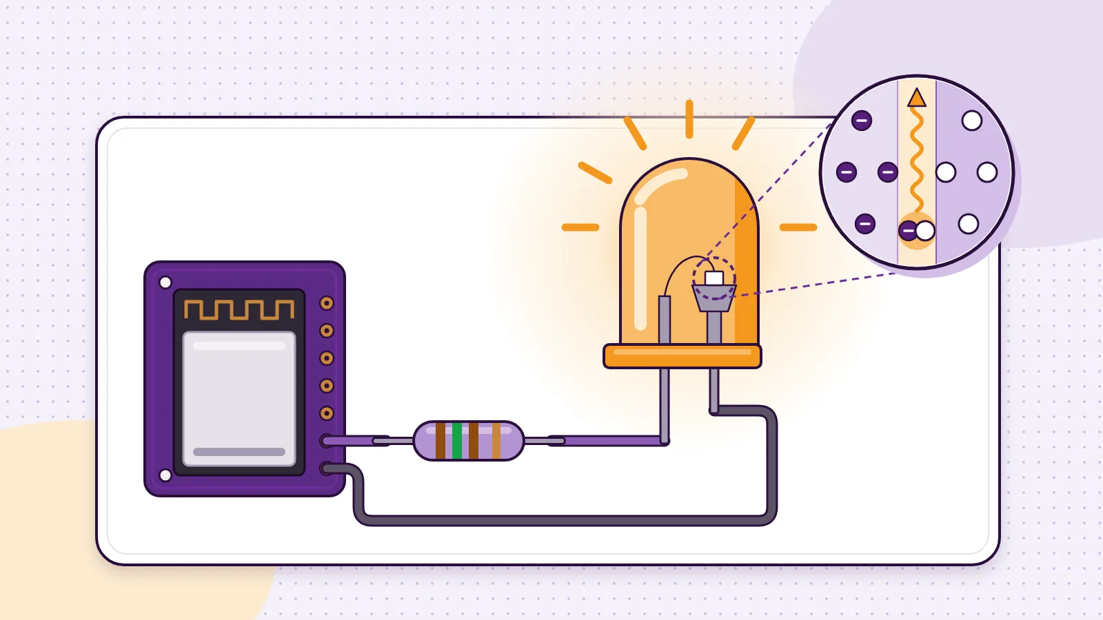
How do LEDs work? An LED, or light-emitting diode, is a tiny sandwich of semiconductor layers. When current flows through it the right way, electrons from one layer meet gaps called holes from the other. Each meeting gives off a small packet of light called a photon. The material of the layers decides the colour. Because an LED is a diode, current can only flow one way, so it has a positive leg and a negative leg. And once it lights, almost nothing inside it holds the current back, so it needs a resistor in series to keep the current safe.
Below you get a colour chart with real datasheet numbers, a worked example that picks the resistor for a blue LED, PWM dimming and the mistakes beginners make most. Then try it all in Lesson 4, Hello World and PWM Dimming, which has a Try it demo that runs in your browser.
What is an LED, and how is it different from a light bulb?
LED stands for light-emitting diode. A diode lets current through in one direction only, like a one-way door. A light-emitting diode is a diode built so that the current passing through it makes light. Our guide to diode types and uses covers the rest of the family.
You meet LEDs all day, from the power light on a charger to the screen you are reading. The Nobel Prize's popular information on the 2014 physics prize (opens in a new tab) notes that LEDs light the LCD screens in televisions, computers and mobile phones, and give phones their camera flash.
The big difference from an old bulb is how the light is made. A bulb heats a thin wire until it glows, so most of the energy leaves as heat. In an LED, electricity becomes light directly.
| Light source | How it makes light | Light per watt of power | Typical life |
|---|---|---|---|
| Incandescent bulb | Current heats a wire filament until it glows | 16 lumens per watt | About 1,000 hours, until heat destroys the filament |
| Fluorescent lamp | A gas discharge makes heat and light | Close to 70 lumens per watt | Around 10,000 hours |
| LED lamp | Electricity becomes photons directly | Just over 300 lumens per watt, a 2014 record | Up to 100,000 hours |
- Light source
- Incandescent bulb
- How it makes light
- Current heats a wire filament until it glows
- Light per watt of power
- 16 lumens per watt
- Typical life
- About 1,000 hours, until heat destroys the filament
- Light source
- Fluorescent lamp
- How it makes light
- A gas discharge makes heat and light
- Light per watt of power
- Close to 70 lumens per watt
- Typical life
- Around 10,000 hours
- Light source
- LED lamp
- How it makes light
- Electricity becomes photons directly
- Light per watt of power
- Just over 300 lumens per watt, a 2014 record
- Typical life
- Up to 100,000 hours
Table note: all figures are from the Nobel Prize's popular information (opens in a new tab), written in 2014. The 300 lumens per watt was a record then, not what an ordinary shop bulb gives. The same page adds that LED lamps, unlike fluorescent lamps, contain no mercury.
How do LEDs work? Electrons, holes and light
The Nobel Prize's popular information (opens in a new tab) describes an LED as several layers of semiconductor, from the same branch of engineering that gave us computers and mobile phones. Here is what happens, step by step.
- 1
Two different layers.
The n-type layer has spare electrons. The p-type layer is short of electrons. Each missing electron is called a hole, and it acts like a small positive charge.
- 2
A middle layer.
Between the two sits a thin active layer.
- 3
A push.
Connect a voltage the right way round and it drives electrons and holes into the active layer.
- 4
Light.
When an electron meets a hole, they recombine, and the energy the electron gives up leaves as a photon.
- 5
Colour.
The same page says the light's wavelength depends entirely on the semiconductor. Change the material and you change the colour.
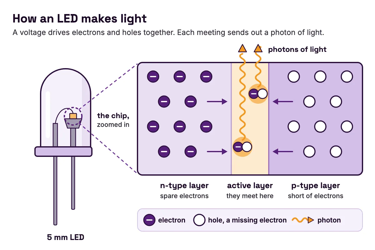
SparkFun's LED tutorial (opens in a new tab) puts it simply: in most diodes that energy leaves as heat, but in an LED it leaves as light.
One more idea matters: forward voltage. The LED needs a minimum push before current flows in earnest. Below it, the LED stays dark. Above it, the current climbs fast. Every LED datasheet lists this forward voltage, and it is the key number when you choose a resistor.
Why blue LEDs won a Nobel Prize
The Nobel Prize's popular information (opens in a new tab) says the red LED was invented at the end of the 1950s and used in digital watches, calculators and on/off lights. Blue was much harder. The 2014 press release (opens in a new tab) says it remained a challenge for three decades, until Isamu Akasaki, Hiroshi Amano and Shuji Nakamura made bright blue LEDs in the early 1990s. The popular information page adds that all three worked with gallium nitride.
Without blue there is no white LED lamp. The popular information page (opens in a new tab) gives two ways to make white: shine blue light on a coating called a phosphor so it glows red and green, or put red, green and blue LEDs together and let your eye mix them. See RGB LEDs and colour mixing for the second idea.
LED colours compared: material, wavelength and forward voltage
Different materials give different colours, and they need a different push. The table compares five 5 mm LEDs from one maker, Kingbright, so you compare like with like.
| Colour | Kingbright part | Chip material | Peak wavelength | Forward voltage, typical (max) | Measured at | Max steady current |
|---|---|---|---|---|---|---|
| Red | WP7113ID | GaAsP on GaP | 627 nm | 1.9 V (2.3 V) | 10 mA | 30 mA |
| Yellow | WP7113YD | GaAsP on GaP | 590 nm | 1.95 V (2.4 V) | 10 mA | 30 mA |
| Green | WP7113GD | GaP | 565 nm | 2.0 V (2.4 V) | 10 mA | 25 mA |
| Blue | WP7113QBC/D | InGaN | 460 nm | 3.3 V (4.0 V) | 20 mA | 30 mA |
| White | WP7113QWC/D | InGaN | Mixed, no single colour | 3.3 V (4.0 V) | 20 mA | 30 mA |
- Colour
- Red
- Kingbright part
- WP7113ID
- Chip material
- GaAsP on GaP
- Peak wavelength
- 627 nm
- Forward voltage, typical (max)
- 1.9 V (2.3 V)
- Measured at
- 10 mA
- Max steady current
- 30 mA
- Colour
- Yellow
- Kingbright part
- WP7113YD
- Chip material
- GaAsP on GaP
- Peak wavelength
- 590 nm
- Forward voltage, typical (max)
- 1.95 V (2.4 V)
- Measured at
- 10 mA
- Max steady current
- 30 mA
- Colour
- Green
- Kingbright part
- WP7113GD
- Chip material
- GaP
- Peak wavelength
- 565 nm
- Forward voltage, typical (max)
- 2.0 V (2.4 V)
- Measured at
- 10 mA
- Max steady current
- 25 mA
- Colour
- Blue
- Kingbright part
- WP7113QBC/D
- Chip material
- InGaN
- Peak wavelength
- 460 nm
- Forward voltage, typical (max)
- 3.3 V (4.0 V)
- Measured at
- 20 mA
- Max steady current
- 30 mA
- Colour
- White
- Kingbright part
- WP7113QWC/D
- Chip material
- InGaN
- Peak wavelength
- Mixed, no single colour
- Forward voltage, typical (max)
- 3.3 V (4.0 V)
- Measured at
- 20 mA
- Max steady current
- 30 mA
Table note: every value comes from the Kingbright datasheets for the red WP7113ID (opens in a new tab), yellow WP7113YD (opens in a new tab), green WP7113GD (opens in a new tab), blue WP7113QBC/D (opens in a new tab) and white WP7113QWC/D (opens in a new tab). Other LEDs differ, so check the datasheet for the one in your hand.
Three patterns stand out.
- Bluer light needs a bigger push. Red, yellow and green light at about 2 V. Blue and white need about 3.3 V. The Nobel Prize's popular information (opens in a new tab) calls blue light's photons highly energetic, and making them takes a bigger push.
- Blue and white share a material. Both are InGaN, a gallium nitride alloy, so their forward voltages match.
- The limit is about 30 mA. Each LED allows 25 to 30 mA of steady current at most, and its datasheet tests it at just 10 or 20 mA.
LED polarity: how to find the positive and negative legs
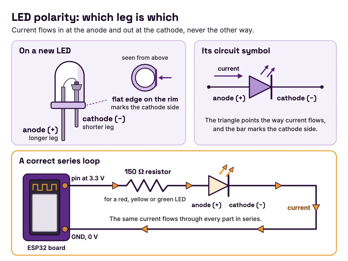
LED polarity means the LED has a positive and a negative side and works only one way round. SparkFun's LED tutorial (opens in a new tab) names them.
- The anode is the positive side. On a new LED it has the longer leg.
- The cathode is the negative side, with the shorter leg.
- Current flows from the anode to the cathode, never the other way.
Legs get trimmed, so you need other clues. SparkFun's polarity guide (opens in a new tab) says the leg nearest the flat edge of the plastic rim is the cathode. For a test, set a multimeter to its diode setting and touch the probes to the legs: if the LED lights, the positive probe is on the anode. Our beginner's guide to the multimeter shows that setting. In a circuit drawing, the LED symbol is a triangle pointing the way current flows, with a bar on the cathode side.
Put it in backwards and SparkFun's LED tutorial (opens in a new tab) says it simply will not work: it blocks the current and stays dark, without breaking. That holds at learning-kit voltages. The Kingbright datasheets, such as the red WP7113ID (opens in a new tab), allow at most 5 V in reverse, so never put more than that across one backwards.
On the MakerBuddy board you can skip this at first. The blue LED and the colour LED are built in and already wired, so there is nothing to plug in the wrong way. Polarity matters the moment you wire a loose LED of your own.
Why LEDs need a resistor
Here is the heart of it. A resistor obeys Ohm's law: double the voltage and you double the current, in a straight line. An LED does not.
Look at the current curve in Kingbright's blue LED datasheet (opens in a new tab). Read by eye, the current is close to zero at 2.4 V, about 10 mA near 3.0 V and 30 mA, the LED's limit, by about 3.5 V. About one volt takes it from dark to its maximum, and the curve keeps getting steeper.
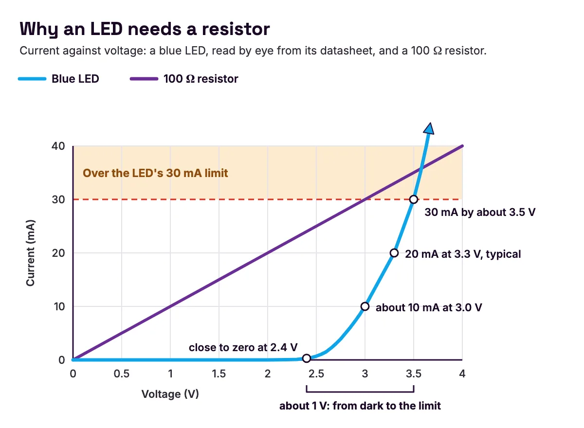
So nothing inside an LED sets a safe current. Connect it straight to a supply above its forward voltage and the current rises until something gives: the LED, the pin or the battery. SparkFun's tutorial (opens in a new tab) warns that an LED with no current-limiting resistor will try to draw as much power as it can and destroy itself. Kingbright's blue LED datasheet (opens in a new tab) adds that too much current can cause severe light loss or early failure.
Heat makes it worse. The red (opens in a new tab) and blue (opens in a new tab) datasheets give the forward voltage falling by about 1.9 mV and 3.0 mV for every degree the LED warms. On a fixed voltage, a warmer LED draws more current, which warms it more.
A resistor in series fixes both problems. It takes up the voltage the LED does not use, and because its own current changes in a straight line, it holds the current near the value you chose. That also sets the brightness. SparkFun's LED tutorial (opens in a new tab) says brightness depends directly on current, and the blue datasheet's (opens in a new tab) brightness curve is close to a straight line: half the current, about half the light.
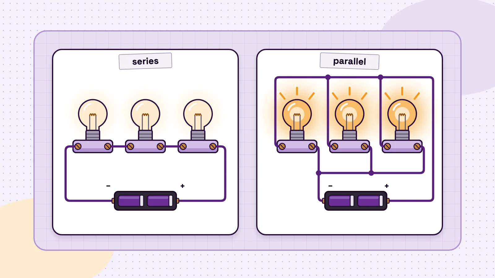
Does the resistor go before or after the LED? Either. SparkFun's series and parallel tutorial (opens in a new tab) says parts in series have the same current flowing through them. More in series vs parallel circuits.
Worked example: choosing the resistor for a blue LED
The LED takes its forward voltage, the resistor takes the rest, and Ohm's law gives the resistor:
Resistor = (supply voltage − LED forward voltage) ÷ current
We use a blue LED because it shows something a red one hides. The numbers come from Kingbright's WP7113QBC/D datasheet (opens in a new tab): 3.3 V typical and 4.0 V maximum at 20 mA, a 30 mA limit and 120 mW of power at most.
Part 1: a blue LED on 5 V
- 1
Voltage left for the resistor
5.0 − 3.3 = 1.7 V.
- 2
Resistance for 20 mA
1.7 V ÷ 0.020 A = 85 Ω.
- 3
Round up to a value you can buy
100 Ω. Rounding up lowers the current, the safe direction.
- 4
Check the current
1.7 ÷ 100 = 0.017 A, or 17 mA. Under the limit.
- 5
Check the spread
at the 4.0 V maximum, 1.0 ÷ 100 = 10 mA, still bright. For an LED a little under typical, at 3.2 V, 1.8 ÷ 100 = 18 mA, still safe.
- 6
Check the power
the resistor uses 1.7 V × 0.017 A = 0.029 W. SparkFun's electric power tutorial (opens in a new tab) says most resistors are rated from 1/8 W to 1/2 W, so a small one copes. The LED uses 3.3 × 0.017 = 0.056 W, under its 120 mW limit.
Part 2: the same LED on a 3.3 V ESP32 pin
An ESP32's pins switch between 0 V and 3.3 V. The rule gives 3.3 − 3.3 = 0 V left, and 0 V ÷ 0.020 A = 0 Ω. There is no room at all.
The LED still lights, because its forward voltage is lower at lower currents. On the datasheet's curve (opens in a new tab), read by eye, it passes about 5 mA at roughly 2.8 V. With 100 Ω, (3.3 − 2.8) ÷ 100 = 0.005 A, which agrees with the curve. So you get about 5 mA and, from the brightness curve, about a quarter of the light it gives at 20 mA. That is fine for a status light.
The catch is that with half a volt to spare, small differences swing the current a long way, and the pin's voltage is not fixed either. Espressif's ESP32 datasheet (opens in a new tab) only promises a high pin at 0.8 times its 3.3 V supply or more, which is 2.64 V. For a bright blue or white LED, power it from 5 V and let the pin switch it through a transistor, as our guide to the transistor as a switch explains.
The resistor for each colour
The same sums for every LED in the colour table give this chart. Red, yellow and green aim for 10 mA, and blue and white for 20 mA, the currents their datasheets test at.
| Colour | Typical forward voltage | Target current | On a 3.3 V pin (ESP32) | On 5 V (USB, Arduino Uno) |
|---|---|---|---|---|
| Red | 1.9 V | 10 mA | 150 Ω, giving 9.3 mA | 330 Ω, giving 9.4 mA |
| Yellow | 1.95 V | 10 mA | 150 Ω, giving 9.0 mA | 330 Ω, giving 9.2 mA |
| Green | 2.0 V | 10 mA | 150 Ω, giving 8.7 mA | 330 Ω, giving 9.1 mA |
| Blue | 3.3 V | 20 mA | No headroom; about 100 Ω for a dim 5 mA | 100 Ω, giving 17 mA |
| White | 3.3 V | 20 mA | No headroom; about 100 Ω for a dim 5 mA | 100 Ω, giving 17 mA |
- Colour
- Red
- Typical forward voltage
- 1.9 V
- Target current
- 10 mA
- On a 3.3 V pin (ESP32)
- 150 Ω, giving 9.3 mA
- On 5 V (USB, Arduino Uno)
- 330 Ω, giving 9.4 mA
- Colour
- Yellow
- Typical forward voltage
- 1.95 V
- Target current
- 10 mA
- On a 3.3 V pin (ESP32)
- 150 Ω, giving 9.0 mA
- On 5 V (USB, Arduino Uno)
- 330 Ω, giving 9.2 mA
- Colour
- Green
- Typical forward voltage
- 2.0 V
- Target current
- 10 mA
- On a 3.3 V pin (ESP32)
- 150 Ω, giving 8.7 mA
- On 5 V (USB, Arduino Uno)
- 330 Ω, giving 9.1 mA
- Colour
- Blue
- Typical forward voltage
- 3.3 V
- Target current
- 20 mA
- On a 3.3 V pin (ESP32)
- No headroom; about 100 Ω for a dim 5 mA
- On 5 V (USB, Arduino Uno)
- 100 Ω, giving 17 mA
- Colour
- White
- Typical forward voltage
- 3.3 V
- Target current
- 20 mA
- On a 3.3 V pin (ESP32)
- No headroom; about 100 Ω for a dim 5 mA
- On 5 V (USB, Arduino Uno)
- 100 Ω, giving 17 mA
Table note: forward voltages are the typical values from the Kingbright (opens in a new tab) datasheets above, and each resistor is the next common value up. The 5 V column fits an Arduino Uno pin: the UNO R3 datasheet (opens in a new tab) lists its logic reference, IOREF, as connected to 5 V. Our LED resistor formula and chart covers more supplies, and Ohm's law with real examples explains the rule.
Dimming an LED with PWM
You can dim an LED with a bigger resistor, so less current flows. Or you can keep the resistor and switch the LED fully on and off, very fast. That second way is PWM, pulse width modulation, and it is how microcontrollers dim LEDs.
The share of time the LED is on is the duty cycle. Espressif's LEDC reference for Arduino-ESP32 (opens in a new tab) says analogWrite runs from 0, always off, to 255, always on. The core's source code (opens in a new tab) sets its default to 1,000 cycles a second at 8-bit resolution, which is what the MakerBuddy firmware uses for its blue LED. Your eye cannot follow 1,000 flashes a second, so it sees the average.
Here is the sum for PWM 64:
- 1
Duty cycle
64 ÷ 255 = 0.251, about 25%.
- 2
One cycle
1 ÷ 1,000 = 0.001 seconds, or 1 ms.
- 3
On and off
on for about 0.25 ms, off for about 0.75 ms, every cycle.
- 4
Average current
with 17 mA while on, as in the 5 V example, 17 × 0.251 is about 4.3 mA.
PWM does not replace the resistor. During every "on" moment the full current flows, so that moment must be safe on its own.
Lesson 4 adds a twist: at 50% duty the LED gives half the light, but it usually looks brighter than half. Our guide to PWM with an LED explores why.
Try it on MakerBuddy: Lesson 4 and the Try it demo
The MakerBuddy IoT Kit is a learning board built around an ESP32. Its blue LED sits on GPIO 12, next to the printed label 12-LED, and it is already wired, so you control it from the browser dashboard with no wiring and no code. The technical details list every built-in part and its pin.
Lesson 4, Hello World and PWM Dimming is a 45 to 60 minute lesson in Term 1. Its Try it demo runs in your browser, so you can practise without a kit. It shows a drawing of the board and the same LED Control card as the real dashboard, draws the LED pin's PWM signal slowed down 1,000 times, and ticks off each task as you finish it. For how far simulators can take you, see ESP32 and Arduino simulators.
On the real board:
- 1
Find the LED
next to the label 12-LED.
- 2
Open the LED Control card
on the dashboard. It has an LED On/Off switch and a Brightness (PWM) slider.
- 3
Switch the LED on.
It lights almost at once. Click quickly a few times and it keeps up.
- 4
Set three levels.
Slide to PWM 26 (about 10%), then 128 (about 50%), then 255 (100%). Divide the PWM number by 255 to get the share.
- 5
Slide slowly from 0 to 255 and back.
The light changes smoothly.
- 6
Send SOS.
Three short, three long, three short: dots of about 0.5 seconds, dashes of about 1.5 seconds. Can a classmate who cannot see your screen read it?
- 7
Add the knob.
On the Potentiometer Mapping card, choose LED PWM. The turning knob now sets the brightness from 0 to 255.
When you move on to code, analogWrite(12, value) is the same call the firmware uses, and our guide to programming an ESP32 with the Arduino IDE shows the setup. Uploading your own sketch replaces the MakerBuddy firmware until you upload it again; Install by USB explains how to put it back.
Lesson 5, The Physics of Color moves on to the colour LED. New to all of this? Start with our 12 basic electronics ideas for beginners. Schools and families can see what comes in the box on the MakerBuddy kit page.
Common LED mistakes, with causes and fixes
The LED flashed brightly, then went dark for good
Cause: No resistor. The current shot past the 25 to 30 mA limits in Kingbright's green (opens in a new tab) and red (opens in a new tab) datasheets and burned the LED out.
Fix: Use a new LED with a resistor in series: 150 Ω on 3.3 V or 330 Ω on 5 V suits a red, yellow or green LED.
The LED stays dark
Cause: It is in backwards, the loop is not complete, or a blue or white LED is on a supply too close to its forward voltage.
Fix: Put the longer leg, the anode, towards the positive side. Trace the path from the pin, through the resistor and LED, back to ground. For blue or white on 3.3 V, try 100 Ω or move to 5 V.
The LED is far too dim
Cause: The resistor is much bigger than you meant. Brown, black, orange is 10 kΩ, not 100 Ω. A red LED on 3.3 V then gets roughly (3.3 − 1.9) ÷ 10,000 = 0.14 mA, over 60 times less than with 150 Ω.
Fix: Read the colour bands again, or measure the resistor with a multimeter first.
Several LEDs share one resistor and glow unevenly
Cause: LEDs in parallel get the same voltage, but no two need quite the same. The red datasheet (opens in a new tab) allows up to 2.3 V for a part that is typically 1.9 V. The LED needing the least voltage hogs the current.
Fix: Give each LED its own resistor.
A blue or white LED died before you used it
Cause: Static electricity. Kingbright rates its blue LED (opens in a new tab) to survive static discharges of only 250 V, against 8,000 V for its red LED (opens in a new tab).
Fix: The blue LED datasheet (opens in a new tab) recommends a wrist band or anti-static glove, and electrically grounded equipment.
The Brightness (PWM) slider will not move
Cause: The LED is switched off. On the MakerBuddy dashboard the slider only works while the LED is on.
Fix: Turn on the LED On/Off switch first.
FAQ
What happens if you use an LED without a resistor?
If the supply is above the LED's forward voltage, the current climbs until something limits it. Often the LED overheats and dies, sometimes with a bright flash. SparkFun's LED tutorial (opens in a new tab) warns that it will destroy itself. Even when it survives, it is running past its rating and straining the pin or battery.
Is a resistor necessary for every LED?
Something must always limit the current. For a single LED on a pin or battery, that is a resistor. Some LED modules, strips and household bulbs carry their own resistor or driver, so you add nothing. Check the datasheet or listing first.
Should I put the resistor before or after the LED?
Either works. The resistor and LED are in series, and SparkFun's series and parallel tutorial (opens in a new tab) says parts in series carry the same current. So the current is the same on either side.
Do LEDs need a resistor on an ESP32 or Arduino?
Yes. An ESP32 pin gives 3.3 V, and Espressif's datasheet (opens in a new tab) sets each pin's default drive strength at about 20 mA, so 150 Ω suits a red, yellow or green LED. An Arduino Uno works at 5 V, as its UNO R3 datasheet (opens in a new tab) shows, so use 330 Ω there. The LEDs built into the MakerBuddy board are already wired.
What happens if an LED is connected backwards?
It stays dark, because a diode blocks reverse current. SparkFun's LED tutorial (opens in a new tab) says plugging an LED in backwards does not break it; it just will not work. Kingbright's 5 mm LEDs, such as the red WP7113ID (opens in a new tab), allow at most 5 V in reverse. Turn it round and it lights.
How can you tell which side of an LED is positive?
The positive leg, the anode, is the longer one. The negative leg, the cathode, is by the flat edge on the rim. If the legs are cut, use a multimeter's diode setting: SparkFun's polarity guide (opens in a new tab) says the LED lights when the positive probe touches the anode.
How long do LEDs last?
The Nobel Prize's popular information (opens in a new tab) says LEDs can last up to 100,000 hours, against about 1,000 for an incandescent bulb. ENERGY STAR (opens in a new tab) explains that LEDs usually dim slowly rather than burn out, and their rated life ends when the light has dropped by 30 percent. Heat shortens it.
Why do different colour LEDs need different resistors?
Each colour needs a different forward voltage. In Kingbright's datasheets a red LED (opens in a new tab) lights at about 1.9 V and a blue LED (opens in a new tab) at about 3.3 V. More voltage for the LED leaves less for the resistor, so it must change to keep the same current. More guides like this are on the MakerBuddy blog.
Sources
- Nobel Prize: The Nobel Prize in Physics 2014, popular information (opens in a new tab)
- Nobel Prize: The 2014 Nobel Prize in Physics, press release (opens in a new tab)
- SparkFun: Light-Emitting Diodes (LEDs) (opens in a new tab)
- SparkFun: Polarity, diode and LED polarity (opens in a new tab)
- SparkFun: Series and Parallel Circuits (opens in a new tab)
- SparkFun: Electric Power (opens in a new tab)
- Kingbright: WP7113ID 5 mm red LED datasheet (opens in a new tab)
- Kingbright: WP7113YD 5 mm yellow LED datasheet (opens in a new tab)
- Kingbright: WP7113GD 5 mm green LED datasheet (opens in a new tab)
- Kingbright: WP7113QBC/D 5 mm blue LED datasheet (opens in a new tab)
- Kingbright: WP7113QWC/D 5 mm white LED datasheet (opens in a new tab)
- ENERGY STAR: Learn About LED Lighting (opens in a new tab)
- Espressif: ESP32 Series datasheet (opens in a new tab)
- Espressif: Arduino-ESP32 LEDC API reference (opens in a new tab)
- Espressif: Arduino-ESP32 core source, esp32-hal-ledc.c (opens in a new tab)
- Arduino: UNO R3 datasheet (opens in a new tab)