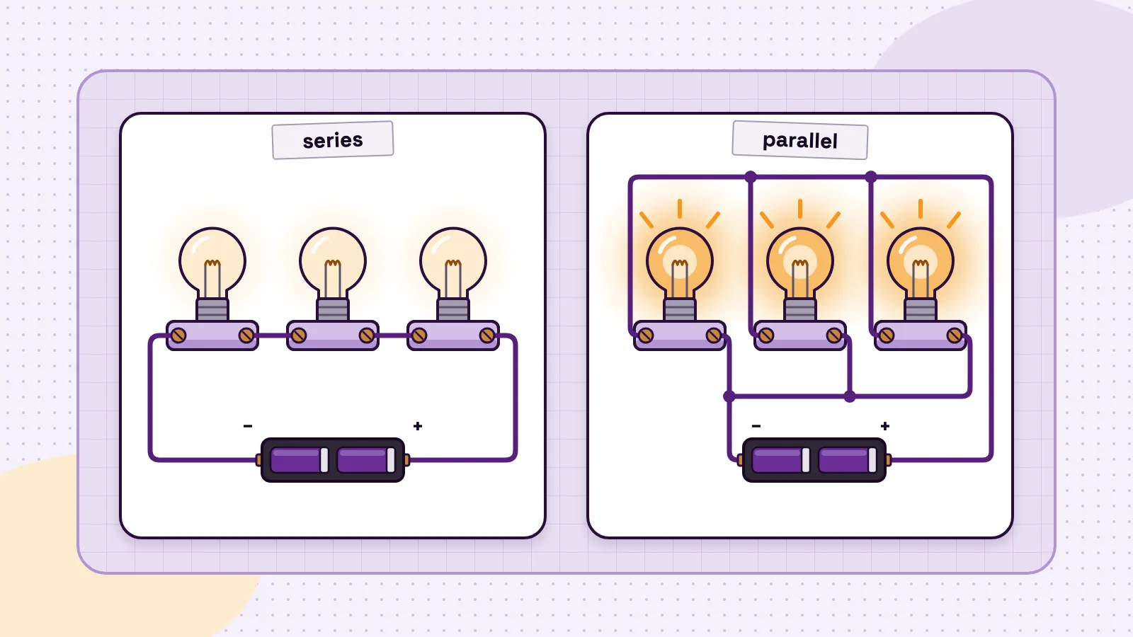
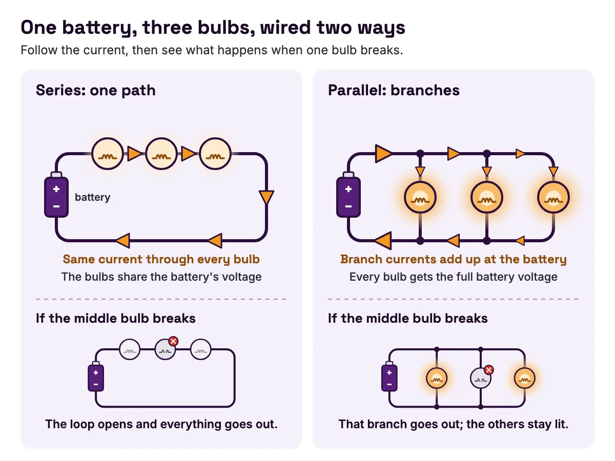
A series circuit connects parts end to end in one loop, so the same current flows through every part and the parts share the supply voltage. A parallel circuit connects each part across the same two points, so every part gets the full supply voltage and the current splits between the branches. That is the whole series vs parallel circuit story in two sentences. In series, one broken part stops everything. In parallel, the other branches keep working.
You will also find both kinds of circuit on a real learning board, the MakerBuddy IoT Kit, and see why its plug-in sensors sit side by side on one 5 V line. If circuits are new to you, start with open, closed and short circuits.
Series vs parallel circuits at a glance
SparkFun's series and parallel circuits tutorial (opens in a new tab) gives a simple test. Two parts are in series when they share one common point and the same current flows through both. They are in parallel when they share two common points, one at each end. The OpenStax College Physics section on resistors in series and parallel (opens in a new tab) gives the rules that follow.
| Feature | Series circuit | Parallel circuit |
|---|---|---|
| Paths for the current | One loop, parts end to end | Two or more branches across the same two points |
| Current | The same through every part | Splits between branches; the branch currents add up to the total |
| Voltage | Shared; the drops add up to the supply voltage | The full supply voltage across every branch |
| Total resistance | The sum of the parts | Less than the smallest branch |
| Add one more part | Total current goes down | Total current goes up |
| One bulb fails | The loop opens and everything goes out | That branch goes out; the others stay lit |
| Everyday example | A switch and the lamp it controls | The lights and sockets in a house |
| How a meter connects | A current meter goes in series | A voltage meter goes in parallel |
- Feature
- Paths for the current
- Series circuit
- One loop, parts end to end
- Parallel circuit
- Two or more branches across the same two points
- Feature
- Current
- Series circuit
- The same through every part
- Parallel circuit
- Splits between branches; the branch currents add up to the total
- Feature
- Voltage
- Series circuit
- Shared; the drops add up to the supply voltage
- Parallel circuit
- The full supply voltage across every branch
- Feature
- Total resistance
- Series circuit
- The sum of the parts
- Parallel circuit
- Less than the smallest branch
- Feature
- Add one more part
- Series circuit
- Total current goes down
- Parallel circuit
- Total current goes up
- Feature
- One bulb fails
- Series circuit
- The loop opens and everything goes out
- Parallel circuit
- That branch goes out; the others stay lit
- Feature
- Everyday example
- Series circuit
- A switch and the lamp it controls
- Parallel circuit
- The lights and sockets in a house
- Feature
- How a meter connects
- Series circuit
- A current meter goes in series
- Parallel circuit
- A voltage meter goes in parallel
The current, voltage, resistance and house wiring rows come from the OpenStax section (opens in a new tab). The meter row comes from SparkFun's guide to using a multimeter (opens in a new tab).
What is a series circuit?
In a series circuit, parts sit one after another, like beads on a string. There is only one path, so every bit of charge that leaves the battery passes through every part before it gets back.
- The current is the same everywhere. OpenStax's resistors in series and parallel section (opens in a new tab) states that the same current flows through each resistor in series. Our guide to electric current explains what that current is.
- The voltage is shared. Each part uses up some of the supply voltage, called its voltage drop. OpenStax shows that the drops add up to the supply voltage exactly, and ties this to conservation of energy.
- Resistance adds up. SparkFun's example (opens in a new tab): 10 kΩ plus 10 kΩ makes 20 kΩ. More resistance means less current, so a third bulb added in series makes all three dimmer.
The single path is also the weakness. If one part breaks, or a wire comes loose, the current stops everywhere.
That weakness is useful too. A switch works because it sits in series with the thing it controls: open the switch and the loop opens. A fuse sits in series for the same reason. A resistor in series with an LED limits its current, as the electronics for beginners guide explains.
What is a parallel circuit?
In a parallel circuit, each part connects across the same two points. Picture a ladder. The side rails are the supply wires, and each rung is a part.
- Every branch gets the full voltage. OpenStax's section on resistors in parallel (opens in a new tab) explains that each resistor in parallel has the full voltage of the source across it.
- The currents add up. The total current from the supply is the sum of the branch currents, which OpenStax links to conservation of charge.
- Total resistance goes down. Each branch is one more path, so the total is always less than the smallest branch. SparkFun's example (opens in a new tab): 10 kΩ in parallel with 10 kΩ makes 5 kΩ.
- Branches work on their own. OpenStax notes that a car's headlights and radio are wired in parallel, and that the same is true in a house.
Parallel has a price. Every branch you add draws more current, so a battery runs down faster and a power supply must deliver the total of all the branches.
Series and parallel formulas in one place
V, I and R stand for voltage in volts, current in amps and resistance in ohms.
SERIES (one path)
  Current:      the same I through every part
  Voltage:      V_supply = V1 + V2 + V3 + ...
  Resistance:   R_total  = R1 + R2 + R3 + ...

PARALLEL (branches across the same two points)
  Voltage:      the same V across every branch
  Current:      I_total = I1 + I2 + I3 + ...
  Resistance:   1 / R_total = 1 / R1 + 1 / R2 + 1 / R3 + ...
  Two resistors only:   R_total = (R1 x R2) / (R1 + R2)
  n equal resistors:    R_total = R / n

OHM'S LAW (for one part, or for the whole circuit)
  V = I x R      I = V / R      R = V / I
The current and voltage rules have names. In the OpenStax section on Kirchhoff's rules (opens in a new tab), the junction rule says the currents flowing into a junction equal the currents flowing out. The loop rule says the voltage changes around any closed loop add up to zero.
SparkFun's series and parallel tutorial (opens in a new tab) warns that the product-over-sum shortcut works for two resistors in one calculation only. Equal resistors in parallel simply divide: its exercise with three, four and five 10 kΩ resistors in parallel should come out at 3.33 kΩ, 2.5 kΩ and 2 kΩ. Every formula here leans on Ohm's law, which our guide to Ohm's law with real examples works through slowly. For what a volt actually is, read voltage explained for students.
Worked example: the same three resistors, wired both ways
Take a 5 V supply, the same voltage a USB cable gives the MakerBuddy board, and three common resistors: 1 kΩ, 2.2 kΩ and 3.3 kΩ.
In series
- 1
Total resistance
1,000 + 2,200 + 3,300 = 6,500 Ω.
- 2
Current
I = V ÷ R = 5 ÷ 6,500 = 0.000769 A, about 0.77 mA, the same in every resistor.
- 3
Voltage across each
V = I × R gives 0.77 V across 1 kΩ, 1.69 V across 2.2 kΩ and 2.54 V across 3.3 kΩ.
- 4
Check
0.77 + 1.69 + 2.54 = 5.00 V. The drops add up to the supply.
The biggest resistor takes the biggest share of the voltage. That is the idea behind a voltage divider, which is how a light sensor turns light into a voltage the board can read.
In parallel
- 1
Voltage
each resistor gets the full 5 V.
- 2
Branch currents
5 ÷ 1,000 = 5.00 mA, 5 ÷ 2,200 = 2.27 mA and 5 ÷ 3,300 = 1.52 mA.
- 3
Total current
5.00 + 2.27 + 1.52 = 8.79 mA.
- 4
Total resistance
5 ÷ 0.00879 = about 569 Ω. The formula agrees: 1/1,000 + 1/2,200 + 1/3,300 = 0.001758, and 1 ÷ 0.001758 = 569 Ω.
569 Ω is less than the smallest resistor, as the rule says. The smallest resistor carries the most current, because it is the easiest path.
Mixed: one in series, two in parallel
Now put the 1 kΩ in series with the other two, which sit in parallel with each other. Work from the inside out.
- 1
The parallel pair
(2,200 × 3,300) ÷ (2,200 + 3,300) = 7,260,000 ÷ 5,500 = 1,320 Ω.
- 2
Total
1,000 + 1,320 = 2,320 Ω.
- 3
Current from the supply
5 ÷ 2,320 = 2.16 mA.
- 4
Voltages
2.16 V across the 1 kΩ, leaving 5 − 2.16 = 2.84 V across the pair.
- 5
Branch currents
2.84 ÷ 2,200 = 1.29 mA and 2.84 ÷ 3,300 = 0.86 mA. Together 2.15 mA; the 0.01 mA gap is rounding.
| Wiring | Total resistance | Current from the 5 V supply | Voltage across the 1 kΩ |
|---|---|---|---|
| All in series | 6,500 Ω | 0.77 mA | 0.77 V |
| All in parallel | 569 Ω | 8.79 mA | 5.00 V |
| 1 kΩ in series with a parallel pair | 2,320 Ω | 2.16 mA | 2.16 V |
- Wiring
- All in series
- Total resistance
- 6,500 Ω
- Current from the 5 V supply
- 0.77 mA
- Voltage across the 1 kΩ
- 0.77 V
- Wiring
- All in parallel
- Total resistance
- 569 Ω
- Current from the 5 V supply
- 8.79 mA
- Voltage across the 1 kΩ
- 5.00 V
- Wiring
- 1 kΩ in series with a parallel pair
- Total resistance
- 2,320 Ω
- Current from the 5 V supply
- 2.16 mA
- Voltage across the 1 kΩ
- 2.16 V
Same parts, same supply, and the current changes more than elevenfold. OpenStax's worked examples (opens in a new tab) show the same effect at a bigger scale: its 1.00 Ω, 6.00 Ω and 13.0 Ω resistors on 12.0 V draw 0.600 A in series and 14.92 A in parallel. On a real breadboard your readings will be close, not exact, because resistors have a tolerance.
How to tell if a circuit is series or parallel
Real circuits often mix both, so read them one piece at a time.
- 1
Trace the path.
Put a finger on the positive side of the supply and follow the wire. If the path never splits before it gets back, every part on it is in series.
- 2
Find the junctions.
A junction is a point where three or more wires meet. A split means branches.
- 3
Use the two-points test.
If both ends of two parts connect to the same two points, they are in parallel.
- 4
Try the removal test.
With the power off, take one part out, then power on. If everything stops, that part was in series with the rest. If the others keep working, it was a parallel branch.
- 5
Measure.
In voltage mode, hold the probes across each part. Parallel parts all show the supply voltage; series parts show smaller voltages that add up to it. For current, SparkFun's multimeter guide (opens in a new tab) explains that you must interrupt the circuit and put the meter in line. Our beginner's guide to using a multimeter walks through both.
For a mixed circuit, replace each parallel group with its single total, as in the worked example. What is left is often a simple series loop.
Batteries, bulbs and switches in series and parallel
Batteries
Battery University's guide to series and parallel battery configurations (opens in a new tab) explains that cells in series add their voltages while the capacity stays the same. Cells in parallel keep the same voltage while the capacity, and so the runtime, goes up. Its laptop example puts two cells in parallel to boost the capacity from 2,400 mAh to 4,800 mAh. So two 1.5 V cells in series give 3 V, while in parallel they give 1.5 V for longer. The guide also says never to mix different makes and sizes of cell, because in series the weakest cell drags the whole pack down.
Bulbs
Two identical bulbs in series on one battery each get about half the voltage, so both glow dimmer than one bulb alone, and unscrewing one puts both out. In parallel each gets the full voltage and glows as brightly as a single bulb, and unscrewing one leaves the other lit. But the battery now feeds two bulbs, so it runs down sooner.
Switches: series means AND, parallel means OR
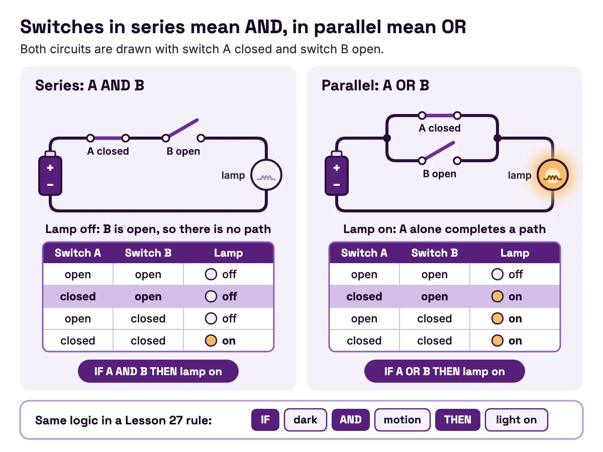
Put two switches in series with a lamp, and the lamp lights only when switch A and switch B are closed. Put them in parallel, and the lamp lights when switch A or switch B is closed, because either one completes a path.
Smart devices decide with the same logic. Lesson 27 teaches MakerBuddy rules that join two sensor tests with AND (both must be true) or OR (either one is enough), such as a light that needs dark AND motion. Our post on if-then statements with real sensors builds rules like these with no code.
Where series and parallel hide on the MakerBuddy board
The MakerBuddy IoT Kit V1.0 is a learning board built around a 30-pin ESP32 DevKit, a small computer with Wi-Fi. The technical details say it runs on 5 V through the DevKit's micro-USB port, with 6 parts built in and 9 that plug into labelled sockets. Lesson 2's board tour sorts the parts into built in and plug in. Look again with series and parallel in mind. The board comes in purple or green, and both colours are the same board.
The plug-in sockets sit in parallel on one 5 V line
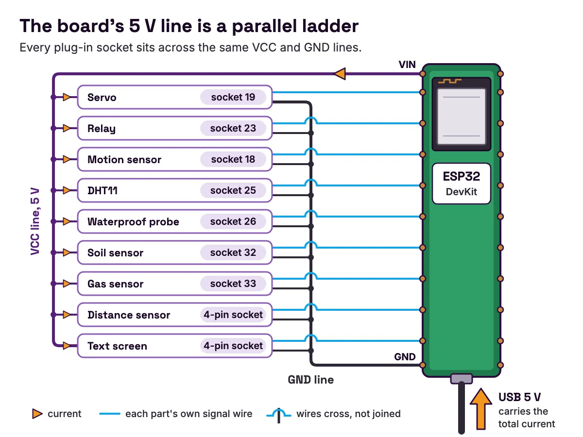
Beside the sockets you will find VCC and GND printed on the board. VCC is the power pin and GND the ground pin. Most sockets have three pins: VCC, GND and a signal pin that goes to one ESP32 pin. The distance sensor and text screen sockets have four.
In the board's V1.0 design, every socket's VCC pin joins one line, and the 5 V from the USB cable reaches it through the DevKit's VIN pin. Every GND pin joins one ground line. Two small four-pin headers labelled VCC and GND bring the same two lines out, and so does the two-pin 5V socket that Lesson 15 uses to power a small lamp.
So the servo in socket 19, the relay in 23, the motion sensor in 18, the DHT11 in 25, the waterproof probe in 26, the soil sensor in 32, the gas sensor in 33, the distance sensor and the text screen all connect across the same two lines. Each one is a rung on the ladder. The power pins are shared, but each part talks to the ESP32 on its own signal pin.
Why parallel?
- Each part needs the full supply voltage. The HC-SR04 datasheet (opens in a new tab) lists a working voltage of DC 5 V, and the MQ-2 datasheet (opens in a new tab) a heater voltage of 5.0 V ± 0.2 V. In series they would have to share the 5 V, and none would get what it needs.
- Each part takes only the current it needs. A sensor that sips a few milliamps does not hold back one that needs more.
- One part can come out without upsetting the rest. With series sockets, an empty socket would open the loop and switch everything off. Still switch off the USB power first, as Lesson 2's safe connection routine says.
- The price is current. Every branch's current adds up in the USB cable, as the next section shows.
Series circuits inside the parts
- The light sensor. Lesson 7 explains that the LDR is wired as a voltage divider: it sits in a row with a fixed resistor, and the voltage between them changes with the light. The dashboard shows it as 0 to 100.
- The gas sensor. The MQ-2 datasheet's (opens in a new tab) test circuit puts the sensing element in series with a load resistor and reads the voltage across that resistor. The heater is a separate circuit beside it, so one small part holds both ideas. Gas sensor builds are learning models, never a real gas or smoke alarm.
- The relay and its lamp. In Lesson 15 you wire the board's 5V plug to the relay's COM terminal, NO to a small 5 V lamp, and the lamp's other lead to GND. The relay's contacts sit in series with the lamp, like a switch. Close them and the loop is complete.
Worked example: adding up current on the board's 5 V line
In parallel, branch currents add. So you can estimate what the USB supply must deliver by adding each part's datasheet figure.
| Part and socket | What its source says | Current from the supply |
|---|---|---|
| HC-SR04 distance sensor | Working current 15 mA at DC 5 V | 15 mA |
| DHT11 sensor (25) | At most 2.5 mA while it takes a reading | 2.5 mA |
| MQ-2 gas sensor heater (33) | Heater 31 Ω ± 3 Ω, at most 900 mW, at 5.0 V | 5.0 ÷ 31 = about 161 mA |
| Subtotal for these three | about 179 mA | |
| ESP32 chip sending Wi-Fi | 240 mA typical, measured on a 3.3 V supply | about 240 mA more, as a rough guide |
- Part and socket
- HC-SR04 distance sensor
- What its source says
- Working current 15 mA at DC 5 V
- Current from the supply
- 15 mA
- Part and socket
- DHT11 sensor (25)
- What its source says
- At most 2.5 mA while it takes a reading
- Current from the supply
- 2.5 mA
- Part and socket
- MQ-2 gas sensor heater (33)
- What its source says
- Heater 31 Ω ± 3 Ω, at most 900 mW, at 5.0 V
- Current from the supply
- 5.0 ÷ 31 = about 161 mA
- Part and socket
- Subtotal for these three
- What its source says
- Current from the supply
- about 179 mA
- Part and socket
- ESP32 chip sending Wi-Fi
- What its source says
- 240 mA typical, measured on a 3.3 V supply
- Current from the supply
- about 240 mA more, as a rough guide
The figures come from the HC-SR04 datasheet (opens in a new tab), Adafruit's DHT guide (opens in a new tab), the MQ-2 datasheet (opens in a new tab) and table 5-4 of Espressif's ESP32 Series datasheet (opens in a new tab).
The heater working, step by step:
- 1
Current
I = V ÷ R = 5.0 ÷ 31 = 0.161 A, about 161 mA.
- 2
Power
P = V × I = 5.0 × 0.161 = 0.81 W, inside the 900 mW limit.
- 3
Spread
the heater can measure from 28 Ω to 34 Ω, so its current lies between 5.0 ÷ 34 = 147 mA and 5.0 ÷ 28 = 179 mA.
The heater outweighs the other two sensors many times over. Espressif measures the ESP32's 240 mA on a 3.3 V supply, after the DevKit has turned the 5 V into 3.3 V, so adding it to the 5 V figures is a rough guide, not an exact sum. Even so, three sensors and the Wi-Fi chip already pass 400 mA. The same ESP32 Series datasheet (opens in a new tab) recommends that the chip's 3.3 V supply can deliver 500 mA or more.
The servo is not in the table because its draw changes with the load, but a stuck servo draws extra current, as the common mistakes below explain. So power the board from a proper 5 V USB source, such as a USB charger, as the MakerBuddy setup checklist asks. Espressif's esptool troubleshooting guide (opens in a new tab) agrees from the chip's side: the 3.3 V supply must handle peaks of 200–300 mA, and a bad-quality USB cable is one cause of the upload errors it lists.
Try it: a 30-minute series and parallel activity
You need one board, the dashboard on a computer, iPhone or iPad, and paper. Android phones cannot control the board yet. No soldering and no code.
- 1
Board hunt (5 minutes).
Find VCC and GND beside the sockets, and the four-pin VCC and GND headers. Ask: if every VCC joins one line and every GND another, is that series or parallel?
- 2
Removal test (10 minutes).
With the USB cable unplugged, plug in the DHT11 and the distance sensor. Power on and open the live sensor cards. Power off, unplug the distance sensor, then power on again and reconnect. The temperature, humidity and light cards keep updating, so the sockets are parallel branches.
- 3
Paper maths (10 minutes).
In pairs, one student works the three resistors in series, the other in parallel. Compare totals.
- 4
Logic link (5 minutes).
Draw two switches in series and two in parallel with a lamp. Write each as a rule: "IF A AND B THEN lamp on" and "IF A OR B THEN lamp on".
With a multimeter and an adult to help, measure in voltage mode between the VCC and GND headers, then across a socket's VCC and GND pins, taking care never to bridge two pins. The readings match, close to 5 V, because every branch sits across the same two lines. The free MakerBuddy curriculum builds on these ideas across 32 lessons for ages 10 and up. If your class has no boards yet, you can order MakerBuddy kits or ask for a quote.
Common mistakes with series and parallel circuits
Adding parallel resistors like series ones
Symptom: your parallel total is bigger than the smallest resistor. Cause: you added the values, which is the series rule, or used product over sum on three resistors at once. Fix: a parallel total is always less than the smallest branch. SparkFun's tutorial (opens in a new tab) warns that 1 kΩ in parallel with 10 kΩ is nowhere near 5 kΩ; product over sum gives 10,000,000 ÷ 11,000 = 909 Ω. Combine resistors two at a time, or use the reciprocal formula.
Blowing the multimeter's fuse
Symptom: after a test, the meter reads 0.00 on every current reading. Cause: in current mode the probes went across the supply, in parallel. SparkFun's multimeter guide (opens in a new tab) says this connects the supply to ground through the meter and blows its fuse. Fix: measure voltage across a part, and current in series, with the meter in a gap in the loop.
The board restarts when the servo moves
Symptom: the board restarts, or the dashboard drops its connection, when the servo starts or gets stuck. Cause: Lesson 14 warns that stuck servo gears can buzz, draw extra current and restart the board. Every socket shares one supply, so a surge in one branch pulls the voltage down for all of them. A weak USB port or a poor cable makes it worse. Fix: use a 5 V USB charger and a good cable, keep the servo arm short and light, and never let it push against an obstacle.
A stray wire across a part
Symptom: one part suddenly stops working and the battery gets warm. Cause: a bare wire or solder blob sits in parallel with the part. It has almost no resistance, so the current takes that path, and by Ohm's law a tiny resistance means a huge current: a short circuit. Fix: power off at once, remove the stray path, and read about short circuits and how to avoid them.
FAQ
What is voltage in a parallel circuit?
Every branch of a parallel circuit has the full supply voltage across it. On a 5 V supply, each branch gets 5 V, whether there is one branch or ten. The current is what changes: each branch draws its own share, and the shares add up at the supply.
How does current flow in series and parallel circuits?
In series there is one path, so the same current flows through every part. In parallel the current splits at each junction, flows through the branches, and joins again on the way back. The branch currents add up to the current leaving the supply.
Why do we not use a series circuit in a house?
In series, every appliance would share the mains voltage, so none would get what it needs. Switching off one lamp, or one bulb failing, would also cut power to everything else on the loop. OpenStax (opens in a new tab) gives house wiring as an example of parallel wiring for this reason.
Is it better to run outlets in series or parallel?
OpenStax (opens in a new tab) notes that the devices in a house are wired in parallel, so each socket gets the full mains voltage and works on its own. In series, every socket would share the voltage, and unplugging one load could cut the rest. Mains wiring is dangerous and is a job for a qualified electrician, never a student project.
Do you get more voltage in series or parallel?
For batteries, series. Cells in series add their voltages, as Battery University's guide (opens in a new tab) explains, so two 1.5 V cells give 3 V, while cells in parallel keep the voltage the same and add capacity. For the parts a circuit powers, parallel gives each one the full supply voltage, while parts in series share it.
What are the advantages and disadvantages of a parallel circuit?
Each branch gets the full voltage, works on its own and can be switched or removed without affecting the others. The downside is current: every branch adds to the total the supply must deliver, so batteries drain faster and a weak supply can sag. A short in one branch can also pull the whole supply down.
What is a series-parallel circuit?
It mixes both. Some parts sit in series and some in parallel, like the 1 kΩ resistor in series with a parallel pair in the worked example above. To solve one, replace each parallel group with its single total, then treat what is left as a series loop.
Why does adding resistors in parallel lower the total resistance?
Each resistor in parallel is another path for the current, like opening another checkout lane in a shop. More paths let more current through at the same voltage, and by Ohm's law that means a lower total resistance. More guides like this one are on the MakerBuddy blog.
Sources
- OpenStax College Physics 2e: 21.1 Resistors in Series and Parallel (opens in a new tab)
- OpenStax College Physics 2e: 21.3 Kirchhoff's Rules (opens in a new tab)
- SparkFun: Series and Parallel Circuits (opens in a new tab)
- SparkFun: How to Use a Multimeter (opens in a new tab)
- Battery University: BU-302 Series and Parallel Battery Configurations (opens in a new tab)
- Elecfreaks: HC-SR04 Ultrasonic Ranging Module datasheet (SparkFun copy) (opens in a new tab)
- MQ-2 Semiconductor Sensor for Combustible Gas datasheet (Pololu copy) (opens in a new tab)
- Adafruit: DHT11, DHT22 and AM2302 Sensors, overview (opens in a new tab)
- Espressif: ESP32 Series datasheet (opens in a new tab)
- Espressif: esptool troubleshooting (opens in a new tab)