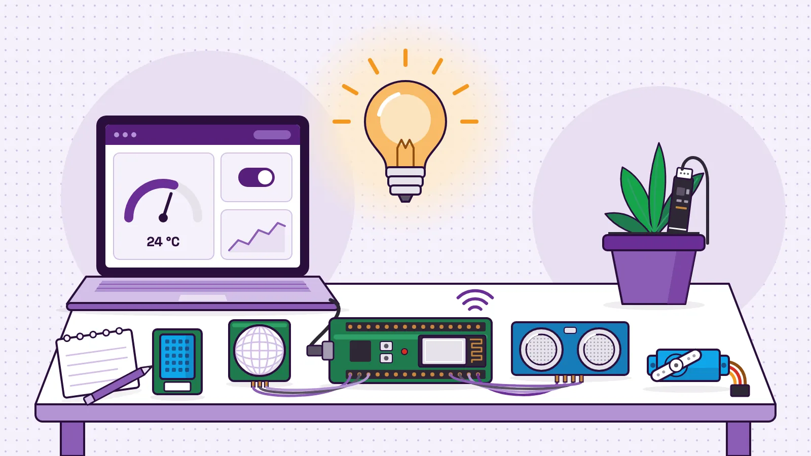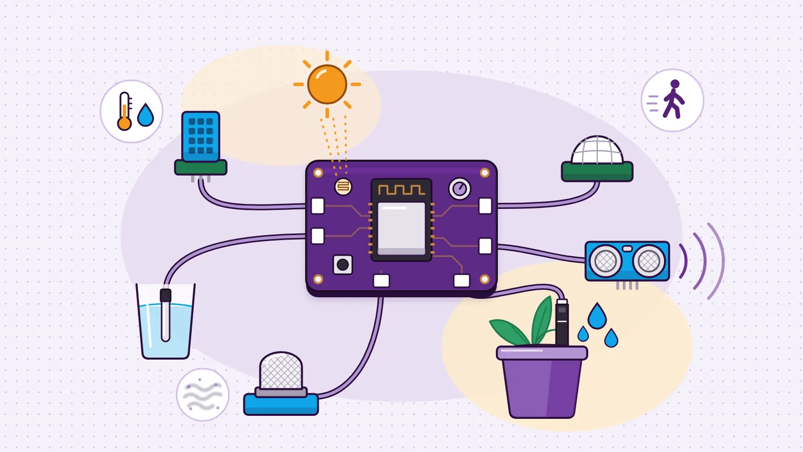
A sensor is a part that notices something in the world, such as light, heat, distance or movement, and turns it into an electrical signal. A small computer, such as the ESP32 on a MakerBuddy board, reads that signal as a number or an on/off value. A program or a rule then decides what to do with it.
There are many types of sensors, but student projects use a small, steady set. You can sort them two ways: by what they measure, and by the kind of signal they send. This guide does both for every sensor in the MakerBuddy kit. For each one you get what the board reports, the live dashboard card where you see the reading, and the lesson that teaches it.
Types of sensors at a glance
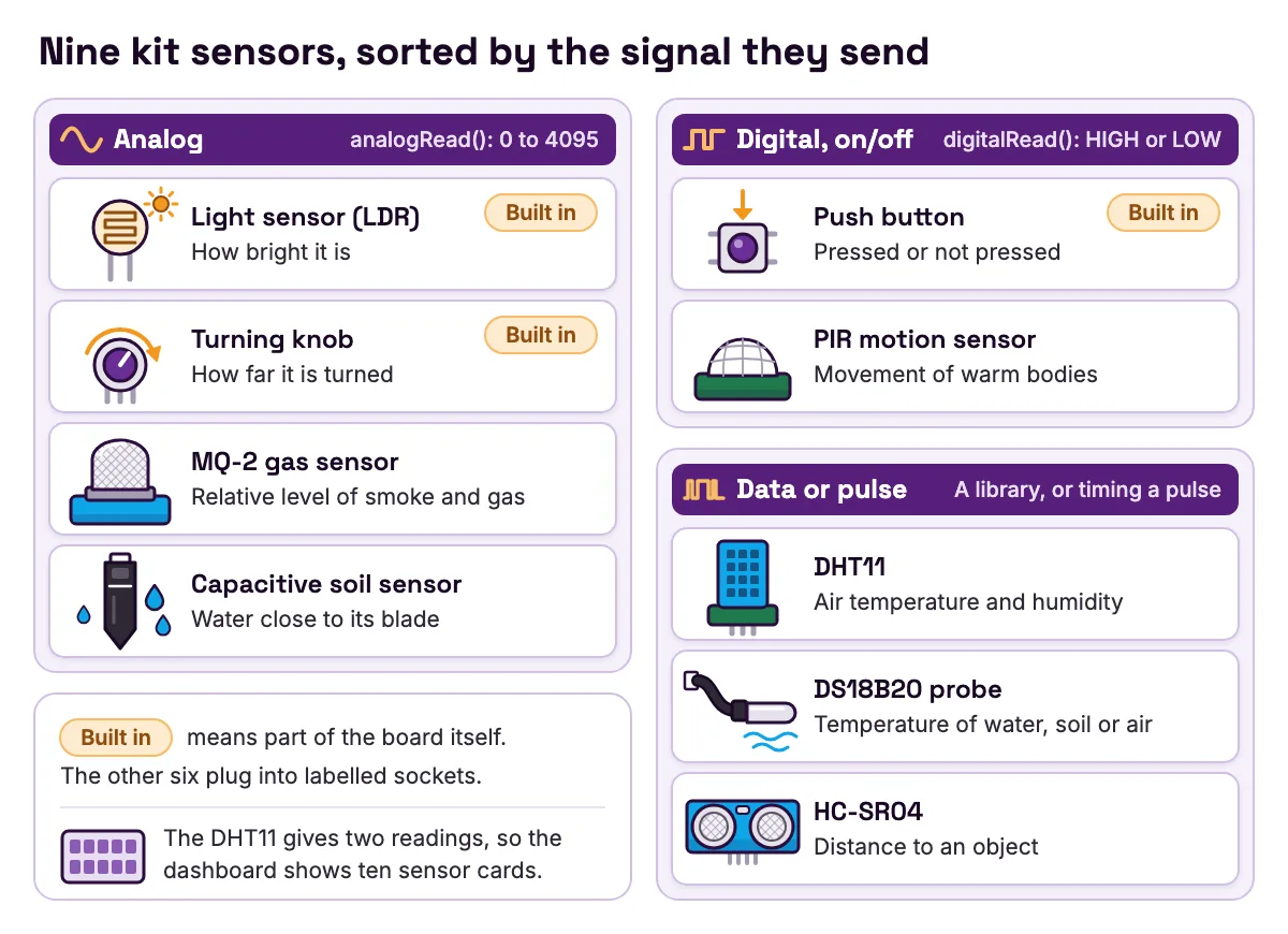
The MakerBuddy IoT Kit V1.0 has nine sensors. Three are built into the board: a light sensor, a push button and a turning knob. Six plug into labelled sockets. The DHT11 gives two readings, so the dashboard shows ten sensor cards.
| Sensor | What it measures | Output type | Example project | Lesson |
|---|---|---|---|---|
| Light sensor (LDR), built in | How bright it is | Analog | Smart Night Light | Week 7 |
| Push button, built in | Pressed or not pressed | Digital, on/off | Doorbell | Week 6 |
| Turning knob (potentiometer), built in | How far it is turned | Analog | Knob Dimmer | Week 9 |
| DHT11 | Air temperature and humidity | Digital data on one pin | Room Thermometer | Week 10 |
| DS18B20 waterproof probe | Temperature of water, soil or air | One-wire digital (1-Wire) | Insulation Tester | Week 11 |
| HC-SR04 | Distance to an object | Pulse (echo time) | Garage Park Assist | Week 12 |
| PIR motion sensor (HC-SR501) | Movement of warm bodies | Digital, on/off | Motion Alarm | Week 13 |
| MQ-2 | Smoke and burnable gas, as a relative level | Analog | Gas Traffic Light (a learning model) | Week 17 |
| Capacitive soil moisture sensor | Water close to its blade | Analog | Plant Thirst Tracker | Week 18 |
- Sensor
- Light sensor (LDR), built in
- What it measures
- How bright it is
- Output type
- Analog
- Example project
- Smart Night Light
- Lesson
- Week 7
- Sensor
- Push button, built in
- What it measures
- Pressed or not pressed
- Output type
- Digital, on/off
- Example project
- Doorbell
- Lesson
- Week 6
- Sensor
- Turning knob (potentiometer), built in
- What it measures
- How far it is turned
- Output type
- Analog
- Example project
- Knob Dimmer
- Lesson
- Week 9
- Sensor
- DHT11
- What it measures
- Air temperature and humidity
- Output type
- Digital data on one pin
- Example project
- Room Thermometer
- Lesson
- Week 10
- Sensor
- DS18B20 waterproof probe
- What it measures
- Temperature of water, soil or air
- Output type
- One-wire digital (1-Wire)
- Example project
- Insulation Tester
- Lesson
- Week 11
- Sensor
- HC-SR04
- What it measures
- Distance to an object
- Output type
- Pulse (echo time)
- Example project
- Garage Park Assist
- Lesson
- Week 12
- Sensor
- PIR motion sensor (HC-SR501)
- What it measures
- Movement of warm bodies
- Output type
- Digital, on/off
- Example project
- Motion Alarm
- Lesson
- Week 13
- Sensor
- MQ-2
- What it measures
- Smoke and burnable gas, as a relative level
- Output type
- Analog
- Example project
- Gas Traffic Light (a learning model)
- Lesson
- Week 17
- Sensor
- Capacitive soil moisture sensor
- What it measures
- Water close to its blade
- Output type
- Analog
- Example project
- Plant Thirst Tracker
- Lesson
- Week 18
The output type matters as much as what the sensor measures. It decides which pin the sensor can use, how the code reads it and what can go wrong. The next sections explain each type, then walk through the sensors one by one.
For builds that combine them, the ESP32 and Arduino project ideas for students are sorted by sensor and difficulty. The MakerBuddy project idea library lists every idea named in the table, with the parts each one needs. More guides like this one are on the MakerBuddy blog.
Sensors and actuators: where IoT sensors fit
Every automatic project has three parts. A sensor notices something. A rule or a program decides. An actuator acts: it lights up, beeps, moves or switches. A night light is the simplest case. The light sensor notices the dark, a rule compares the reading with a level you chose, and the blue light turns on.
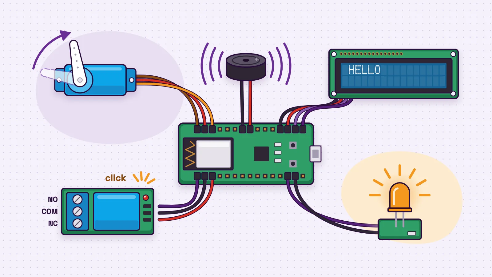
So sensors are inputs and actuators are outputs. The MakerBuddy board has both. The sensors are in this guide. The outputs, from the buzzer to the servo motor and the relay, are in what is an actuator? Motors, relays, buzzers and displays explained.
On MakerBuddy you can build the decision without code. A rule compares one sensor with a number: greater than, less than, at least, at most, or about equal (within 0.1). You can add a second test on the same sensor or another one, joined with AND or OR. The condition has to stay true for 0.3 seconds before the rule starts. Rules work from the board's once-a-second reading, and the motion sensor and button can only be tested as true or false. Week 26, Sensor-Based Control builds rules like these.
What makes these IoT sensors? An IoT sensor is one whose readings travel over a network. The board joins your 2.4 GHz Wi-Fi, reads every sensor once a second and sends the readings to the dashboards about every 2 seconds. Your browser shows them live. There are no accounts, and the readings stay on your own network. The board's web connection has no password, so use it only on a Wi-Fi network you trust. Programmers can read the same values through the board's web API, described in the MakerBuddy REST API documentation.
Analog sensor vs digital sensor
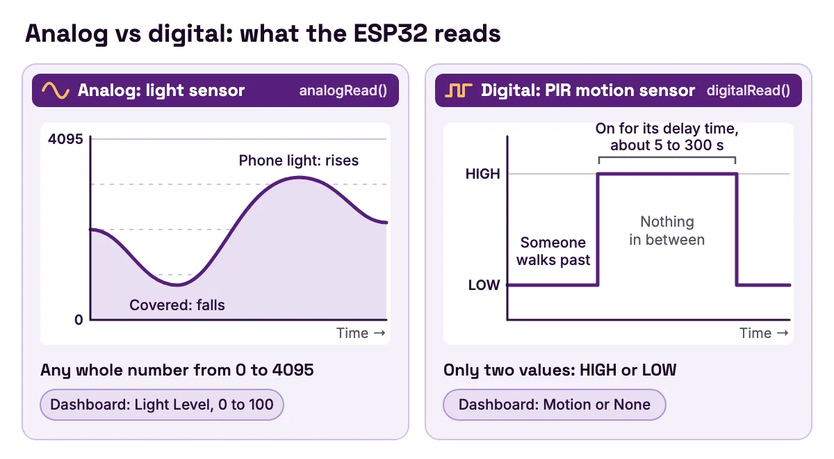
An analog signal can take any value in a range, like a dimmer. A digital signal has a fixed set of values, like a switch that is only on or off. SparkFun's guide to analog and digital signals (opens in a new tab) describes the first as smooth and continuous and the second as discrete. Sensors follow the same split, with a third group that sends coded data or a timed pulse down a digital pin.
The ESP32 reads an analog pin with its analog-to-digital converter, or ADC. In the Arduino core for the ESP32, analogRead() returns a raw 12-bit number from 0 to 4095 by default, according to Espressif's Arduino-ESP32 ADC reference (opens in a new tab). MakerBuddy takes four reads, averages them to smooth out noise, and scales the result to 0–100 for the dashboard.
| Analog | Digital, on/off | Data or pulse | |
|---|---|---|---|
| What the wire carries | A voltage anywhere in a range | High or low, nothing in between | A coded message, or a pulse whose length is the reading |
| How the ESP32 reads it | analogRead(), 0 to 4095 | digitalRead(), HIGH or LOW | A library (DHT, OneWire) or by timing the pulse |
| Kit sensors | Light sensor, knob, MQ-2, soil sensor | Push button, PIR motion sensor | DHT11, DS18B20, HC-SR04 |
| On the dashboard | A level from 0 to 100 | Pressed or Released, Motion or None | °C, humidity, cm |
| Weak spot | Electrical noise, and it often needs calibration | Says yes or no, never how much | Each reading takes time, and a loose wire gives no reading at all |
- What the wire carries
- Analog
- A voltage anywhere in a range
- Digital, on/off
- High or low, nothing in between
- Data or pulse
- A coded message, or a pulse whose length is the reading
- How the ESP32 reads it
- Analog
analogRead(), 0 to 4095- Digital, on/off
digitalRead(), HIGH or LOW- Data or pulse
- A library (DHT, OneWire) or by timing the pulse
- Kit sensors
- Analog
- Light sensor, knob, MQ-2, soil sensor
- Digital, on/off
- Push button, PIR motion sensor
- Data or pulse
- DHT11, DS18B20, HC-SR04
- On the dashboard
- Analog
- A level from 0 to 100
- Digital, on/off
- Pressed or Released, Motion or None
- Data or pulse
- °C, humidity, cm
- Weak spot
- Analog
- Electrical noise, and it often needs calibration
- Digital, on/off
- Says yes or no, never how much
- Data or pulse
- Each reading takes time, and a loose wire gives no reading at all
Why the analog pins matter
The ESP32 has two converters, ADC1 and ADC2. Espressif's ESP-IDF GPIO reference (opens in a new tab) states that "ADC2 pins cannot be used when Wi-Fi is used". MakerBuddy's four analog sensors sit on GPIO 32, 33, 34 and 35, which are all ADC1 channels. So they keep reading while the board is on Wi-Fi. This only becomes your problem when you write your own sketch and move an analog sensor to another pin.
How to tell if a sensor is analog or digital
Look at the pin labels first. Many modules mark an analog output AO or AD and a digital one DO or OUT. In the kit, the MQ-2's adapter is marked AD and the PIR's adapter is marked Out. Then watch the reading. An analog sensor moves smoothly through many values as you change what it senses. An on/off sensor jumps between two.
The three sensors built into the board
The board comes in purple or green. Both colours are the same MakerBuddy IoT Kit V1.0 board. Week 2, the board tour shows every part on it, and the MakerBuddy technical details list each pin.
Light sensor (LDR)
An LDR, or light-dependent resistor, is a resistor whose resistance falls as more light hits it. Adafruit's photocell guide (opens in a new tab) notes that photocells vary by 50% or more, even within one batch. So they are good at telling light from dark, but not at measuring exact brightness.
On MakerBuddy the LDR sits by the 35-LDR label and is read on GPIO 35. The board averages four reads and scales them to 0–100. Low means dark and high means bright.
- Dashboard card: Light Level, from 0 to 100.
- Lesson: Week 7, Light Sensing measures your room in the dark and in bright light, then picks a threshold.
- Try it: the Smart Night Light turns the blue light on when the room gets dark.
Push button
A push button is the simplest digital sensor: pressed or not. The board reads it on GPIO 5 with the ESP32's built-in pull-up resistor switched on (INPUT_PULLUP). So the pin reads high when the button is up and low when it is pressed. That surprises people who write their own code.
- Dashboard card: Push Button, showing Pressed or Released.
- Lesson: Week 6, Digital Inputs.
- Careful: holding the button for 10 seconds erases the saved Wi-Fi name and password. That is how you move the board to a new network.
Turning knob (potentiometer)
A potentiometer is a resistor with a sliding contact. Turning the knob moves the contact, so the voltage on the middle pin moves smoothly from low to high. It senses position, not the outside world. It is the easiest way to watch an analog value change under your fingers.
The board reads it on GPIO 34, averages four reads and scales them to 0–100. In the dashboard you can also let the knob control the blue light's brightness, the colour light or the servo. After every restart the knob goes back to controlling nothing, on purpose.
- Dashboard card: Potentiometer, from 0 to 100.
- Lesson: Week 9, Analog Inputs.
- Try it: the Knob Dimmer makes the blue light brighter or dimmer.
Temperature and humidity: DHT11 and DS18B20
Two of the kit's sensors measure temperature. They suit different jobs, and comparing them is a lesson in itself.
DHT11 temperature and humidity sensor
The DHT11 measures air temperature and relative humidity. It sends both as digital data over a single data pin. Adafruit's DHT guide (opens in a new tab) gives its range as 0–50 °C with ±2 °C accuracy, and 20–80% humidity with 5% accuracy. It should be read no more than once a second.
The board reads it on GPIO 25, once a second. If a read fails, the board sends 0.0 for that value. A reading of 0.0 °C with 0.0 humidity in a warm room means a failed read, not a frozen room.
- Dashboard cards: Temperature (DHT) in °C, and Humidity in percent.
- Lesson: Week 10, Atmospheric Sensing.
- Try it: a Room Thermometer, or the Auto-Fan, where a rule switches on a small low-voltage fan through the relay when the room warms up.
DS18B20 waterproof temperature probe
The DS18B20 is a digital thermometer sealed in a steel tip on a long cable, so it can go into water or soil. It talks over a 1-Wire bus: one data wire plus ground. Each probe has its own 64-bit code, so several can share one wire. The DS18B20 datasheet (opens in a new tab) lists a range of −55 °C to +125 °C, ±0.5 °C accuracy from −10 °C to +85 °C, and up to 750 ms to finish a 12-bit reading.
That last number explains how MakerBuddy reads it. On GPIO 26, the board asks for a reading, carries on, and collects the result on its next pass a second later. So the slow conversion never holds up the rest of the board. If the probe is unplugged, the board sends 0.0.
- Dashboard card: Temperature (DS18B20), in °C.
- Lesson: Week 11, Precision Temperature compares the probe with the DHT11.
- Try it: the Insulation Tester. Put the probe in a cup of warm water, not hot, and find which wrapping keeps it warm longest.
Distance and motion: HC-SR04 and PIR
HC-SR04 ultrasonic distance sensor
The HC-SR04 measures distance with sound too high for people to hear. The HC-SR04 datasheet (opens in a new tab) describes the steps. A 10 µs pulse on Trig makes it send eight cycles of 40 kHz sound. The Echo pin then stays high for as long as the sound takes to bounce back. Divide that time in microseconds by 58 to get centimetres. The datasheet gives a range of 2 cm to 400 cm and a measuring angle of 15 degrees.
A worked example: an echo that lasts 1,160 µs means 1,160 ÷ 58 = 20 cm. The sound went 20 cm out and 20 cm back.
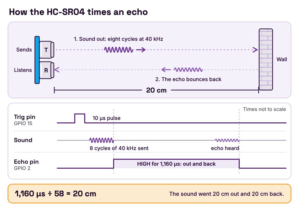
On the board, Trig is GPIO 15 and Echo is GPIO 2. The sensor plugs in with four wires that you match by name. The board stops listening for the echo after 24 ms. That limits how far away an echo can come from, so in practice the board keeps readings from 2 cm to about 4 m. A missed echo keeps the last good distance, and the card shows 999.0 until the first good reading arrives.
- Dashboard card: Distance, in cm.
- Lesson: Week 12, Distance and Echolocation.
- Try it: Garage Park Assist turns the colour light green, then yellow, then red as a car gets closer to the wall.
PIR motion sensor (HC-SR501)
PIR stands for passive infrared. Warm bodies give off infrared light that we cannot see. The sensor has two halves that normally see the same amount. When a warm body moves across, one half sees it before the other, and that difference sets it off, as Adafruit's explanation of how PIRs work (opens in a new tab) shows. It sends nothing out, which is why it is called passive.
The HC-SR501 datasheet (opens in a new tab) gives a range of up to 7 m, set between about 3 m and 7 m with one knob. For the angle it gives two figures, under 120 degrees in one place and under 110 degrees in another. A second knob sets how long the output stays on, from about 5 seconds to 300 seconds. After the output turns off, the sensor ignores everything for 2.5 seconds by default. It needs about a minute after power-on to settle, and may switch on up to three times while it does. It works best when people cross its view, not when they walk straight at it.
On MakerBuddy it is a plain on/off input on GPIO 18. The pin goes high for motion. Ask your teacher before you turn its two knobs.
- Dashboard card: Motion Sensor, showing Motion or None.
- Lesson: Week 13, Security Sensing.
- Try it: the Motion Alarm sounds the buzzer and flashes the blue light when someone walks past.
Gas and soil: MQ-2 and the capacitive soil sensor
MQ-2 smoke and gas sensor
Inside the MQ-2 is a small heater and a layer of tin dioxide. The MQ-2 datasheet (opens in a new tab) explains that the layer conducts poorly in clean air and better as burnable gas increases. It is most sensitive to LPG, propane and hydrogen, and also responds to methane and smoke. The heater runs at 5.0 V ± 0.2 V and can draw up to 900 mW. For its own test figures, the datasheet preheats the sensor for more than 48 hours.
The board reads it on GPIO 33 as an analog value, averaged and scaled to 0–100. That number is a relative level, not parts per million. Record the reading in clean air first, then look for changes from that baseline. The heater is on whenever the board has power, and the metal cover gets hot. Let it warm up for a few minutes before you compare readings.
- Dashboard card: Gas Level (MQ-2), from 0 to 100.
- Lesson: Week 17, Gas and Air Quality, which shows a safe way for a teacher to test it.
- Try it: the Gas Traffic Light, where three rules turn the colour light green, yellow or red as the gas number rises.
Capacitive soil moisture sensor
The kit's soil sensor is a coated blade with no bare metal prongs. No current goes through the soil. Water close to the blade changes how much electric charge the blade can hold, its capacitance. The small circuit at the top turns that into a voltage. DFRobot's guide to a similar capacitive soil moisture sensor (opens in a new tab) says it uses capacitive sensing, not resistive, and is made of corrosion-resistant material. So it does not rust like older two-prong probes. The same guide calibrates the sensor by reading it in dry air and in water.
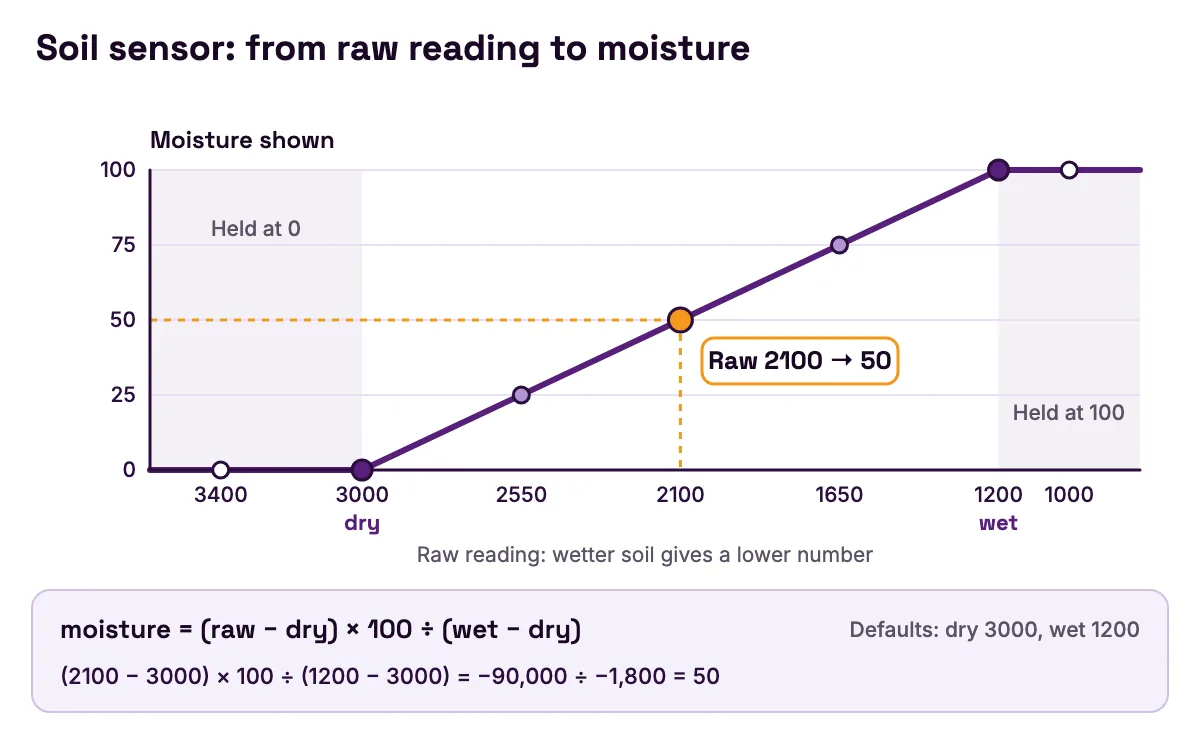
The board reads it on GPIO 32 and averages four reads. It reports two numbers: the raw reading, from 0 to 4095, and a moisture level from 0 to 100. Wetter soil gives a lower raw number. Until you calibrate it, the board treats raw 3000 as dry and raw 1200 as wet.
- Dashboard card: Soil Moisture, from 0 to 100, with a gear button for calibration.
- Lesson: Week 18, Smart Agriculture.
- Try it: the Plant Thirst Tracker beeps or lights up when the plant needs water.
Worked example: from raw number to moisture
The board turns the raw number into moisture with one sum:
moisture = (raw − dry) × 100 ÷ (wet − dry)
Then it holds the answer between 0 and 100 and drops any fraction. With the defaults, dry is 3000 and wet is 1200. A raw reading of 2100 gives (2100 − 3000) × 100 ÷ (1200 − 3000) = −90,000 ÷ −1,800 = 50.
| Raw reading | Sum with the default calibration | Moisture shown |
|---|---|---|
| 3400 | 40,000 ÷ −1,800 = −22.2 | 0 |
| 3000 | 0 ÷ −1,800 = 0 | 0 |
| 2550 | −45,000 ÷ −1,800 = 25 | 25 |
| 2100 | −90,000 ÷ −1,800 = 50 | 50 |
| 2000 | −100,000 ÷ −1,800 = 55.6 | 55 |
| 1650 | −135,000 ÷ −1,800 = 75 | 75 |
| 1000 | −200,000 ÷ −1,800 = 111.1 | 100 |
- Raw reading
- 3400
- Sum with the default calibration
- 40,000 ÷ −1,800 = −22.2
- Moisture shown
- 0
- Raw reading
- 3000
- Sum with the default calibration
- 0 ÷ −1,800 = 0
- Moisture shown
- 0
- Raw reading
- 2550
- Sum with the default calibration
- −45,000 ÷ −1,800 = 25
- Moisture shown
- 25
- Raw reading
- 2100
- Sum with the default calibration
- −90,000 ÷ −1,800 = 50
- Moisture shown
- 50
- Raw reading
- 2000
- Sum with the default calibration
- −100,000 ÷ −1,800 = 55.6
- Moisture shown
- 55
- Raw reading
- 1650
- Sum with the default calibration
- −135,000 ÷ −1,800 = 75
- Moisture shown
- 75
- Raw reading
- 1000
- Sum with the default calibration
- −200,000 ÷ −1,800 = 111.1
- Moisture shown
- 100
Two rows teach the most. At 2000 the true answer is 55.6, but the board shows 55, because whole-number maths drops the fraction. At 3400 and 1000 the reading is outside the dry-to-wet range, so the answer is held at 0 or 100.
Now say your own blade reads 2800 in dry potting mix and 1400 just after watering. You save those two numbers in the dashboard's soil calibration. A raw reading of 2450 now gives (2450 − 2800) × 100 ÷ (1400 − 2800) = 25. With the defaults, the same 2450 would have shown 30. Same soil, same raw number, a different answer. That is why you calibrate for your own soil.
The firmware does this with Arduino's map() and constrain(). Here is the same logic as a small function you can reuse:
// The same sum the MakerBuddy firmware uses. Defaults: dry 3000, wet 1200.
int soilMoisture(int raw, int dry, int wet) {
  if (dry == wet) return 0;               // no range to work with, so the board shows 0
  long pct = map(raw, dry, wet, 0, 100);  // whole-number maths: the fraction is dropped
  return constrain(pct, 0L, 100L);        // hold the answer between 0 and 100
}
Example: read an analog and a digital sensor in Arduino
This sketch reads the built-in light sensor, an analog sensor on GPIO 35, and the plug-in PIR motion sensor, a digital sensor on GPIO 18. It prints both once a second. Set up the Arduino IDE as the documentation describes: the "esp32 by Espressif Systems" boards package (version 3.x), the ESP32 Dev Module board, and the Serial Monitor at 115200 baud.
// MakerBuddy board (ESP32 Dev Module): read one analog and one digital sensor.
// Uploading this replaces the MakerBuddy firmware until you upload that again.

const int LDR_PIN = 35;  // built-in light sensor, analog input on ADC1
const int PIR_PIN = 18;  // plug-in PIR motion sensor (HC-SR501), digital input

// Average four reads, like the MakerBuddy firmware, to smooth out noise.
int readAverage(int pin) {
  long sum = 0;
  for (int i = 0; i < 4; i++) {
    sum += analogRead(pin);  // 0 to 4095 on the ESP32 (12-bit)
  }
  return sum / 4;
}

void setup() {
  Serial.begin(115200);    // match the Serial Monitor speed
  pinMode(PIR_PIN, INPUT); // the PIR drives the pin high or low itself
}

void loop() {
  int lightRaw = readAverage(LDR_PIN);
  int light = map(lightRaw, 0, 4095, 0, 100);  // same 0-100 scale as the Light Level card
  bool motion = digitalRead(PIR_PIN) == HIGH;  // HIGH means the PIR's output is on

  Serial.print("Light raw: ");
  Serial.print(lightRaw);
  Serial.print("   Light 0-100: ");
  Serial.print(light);
  Serial.print("   Motion: ");
  Serial.println(motion ? "YES" : "NO");

  delay(1000);  // once a second, the same pace as the MakerBuddy firmware
}
What each part does:
- 1
readAverage()takes four analog reads and averages them. The MakerBuddy firmware does the same thing to smooth out noise on the ESP32's converter. - 2
analogRead()returns 0 to 4095.map()turns that into the 0–100 scale of the dashboard's Light Level card, so you can compare your numbers with the ones you saw in Week 7. - 3
GPIO 35 needs no
pinMode()line, becauseanalogRead()sets up an analog pin by itself. It is also one of the ESP32's input-only pins, GPIO 34 to 39, according to Espressif's GPIO reference (opens in a new tab), so it could never drive an output anyway. - 4
digitalRead()on GPIO 18 returns HIGH while the PIR's output is on. That is the PIR's own on-time, set by its delay knob, not just the moment you moved. - 5
delay(1000)matches the firmware's once-a-second reading. It also keeps you within the DHT11's limit if you add that sensor later.
Open the Serial Monitor. Cover the light sensor and both light numbers fall. Shine a phone light on it and they rise. Walk across in front of the PIR, not straight at it, and Motion turns YES. In the first minute after power-on, the PIR may say YES on its own while it settles. To add the soil sensor, read GPIO 32 with readAverage() and pass the result to the soilMoisture() function above.
When you finish, put the MakerBuddy firmware back with the steps in install by USB.
Common sensor mistakes and how to fix them
Each mistake below has a symptom you can see, the cause behind it and the fix.
An analog reading stops working when Wi-Fi connects
- Symptom: your own sketch reads an analog sensor fine until it joins Wi-Fi. Then the reading stops making sense.
- Cause: the sensor is on an ADC2 pin. Espressif's GPIO reference (opens in a new tab) says ADC2 pins cannot be used while Wi-Fi is on. On the ESP32, GPIO 2, 15, 25 and 26 are ADC2 pins.
- Fix: use an ADC1 pin. GPIO 32 to 35 are ADC1, which is why MakerBuddy's analog sensors live there. The kit's DHT11, probe and distance sensor use ADC2 pins only as plain digital pins, which is fine.
The gas reading drifts after power-on
- Symptom: the Gas Level card keeps changing for the first few minutes, with nothing in the air.
- Cause: the MQ-2's heater is still warming the sensing layer. The MQ-2 datasheet (opens in a new tab) bases its test figures on more than 48 hours of preheating. It also says a sensor stored unpowered for a long time needs a long ageing time before it is stable.
- Fix: wait a few minutes after power-on, record a clean-air baseline, and compare against that. Never compare a cold sensor with a warm one.
The motion sensor stays on, or misses a second visitor
- Symptom: Motion stays on long after you stop moving, or a person who walks past straight afterwards is not seen.
- Cause: the HC-SR501 holds its output on for its delay time, about 5 to 300 seconds. Then it ignores everything for 2.5 seconds by default, according to the HC-SR501 datasheet (opens in a new tab). The board also checks it once a second, and the dashboard updates about every 2 seconds.
- Fix: time how long it stays on before you build a rule around it. Test by walking across its view, not straight at it.
The DHT11 shows 0.0, or the same number over and over
- Symptom: in your own sketch, the temperature reads NaN or repeats. On the dashboard, it reads 0.0.
- Cause: reading too fast, or a loose plug. Adafruit's DHT guide (opens in a new tab) says to read the DHT11 no more than once a second. MakerBuddy sends 0.0 when a read fails.
- Fix: read it once a second or slower, and check that the plug is pushed fully home.
The distance is stuck at 999.0, or frozen
- Symptom: the Distance card shows 999.0, or holds one number while you move your hand.
- Cause: no good echo came back. 999.0 means none has arrived since power-on. A frozen number is the last good reading, kept after a miss. The HC-SR04 datasheet (opens in a new tab) asks for a smooth target of at least 0.5 square metres, inside a 15-degree cone. Soft, small or angled objects scatter the sound.
- Fix: check the four wires against the Vcc, Trig, Echo and Gnd labels. Then test against a flat book or a wall, face on.
The probe reads 0.0 °C
- Symptom: the Temperature (DS18B20) card shows 0.0.
- Cause: usually the probe is unplugged, and the board sends 0.0 when it gets no answer. But 0.0 can be real. The DS18B20 datasheet (opens in a new tab) range goes down to −55 °C, so a probe in ice water may truly read 0.
- Fix: push the plug in firmly, then hold the steel tip in your hand. The reading should rise.
Soil moisture is stuck at 0 or 100
- Symptom: the Soil Moisture card never moves off 0 or 100.
- Cause: the raw number is outside the dry-to-wet range, so the answer is held at the end. If dry and wet were saved as the same number, moisture always reads 0.
- Fix: calibrate with your own dry and wet readings, as in the worked example above.
The button works backwards in your own code
- Symptom: your sketch says the button is pressed when it is not.
- Cause: the button uses a pull-up resistor, so the pin reads LOW when pressed and HIGH when released.
- Fix: set
pinMode(5, INPUT_PULLUP)and treat LOW as pressed.
When a kit sensor is the wrong tool
Every sensor here is a good teacher and a limited instrument. Know the limits before you trust a reading.
- Precise temperature: the DHT11 is rated ±2 °C in Adafruit's DHT guide (opens in a new tab), and the DS18B20 ±0.5 °C between −10 °C and +85 °C in its datasheet (opens in a new tab). For a science-fair measurement, use the probe.
- Brightness in lux: an LDR cannot measure it, because photocells vary too much from part to part, as Adafruit's photocell guide (opens in a new tab) explains. Treat it as a light-or-dark sensor.
- Gas safety: the MQ-2 gives a relative level, not a calibrated concentration, and MakerBuddy builds with it are learning models. A home or school needs a certified alarm.
- Someone sitting still: a PIR senses warm bodies moving, not people being there. A person reading quietly can vanish from it.
- Soft or narrow targets: the HC-SR04's 15-degree cone and its need for a smooth target, both in the HC-SR04 datasheet (opens in a new tab), make it poor at curtains, fur and thin poles.
- Very quick events: the board reads each sensor once a second, and the dashboard and rules work from that reading. A tap or a hand that flicks past between two reads can be missed. Your own Arduino sketch can read faster.
Do you need a kit at all? Not to start. Every lesson linked in this guide has a Try it demo that runs in the browser. The dashboard also has a demo mode: type demo where it asks for the board's address and you get moving sample readings. Real hardware matters when you want real readings from your own room, garden or classroom. The MakerBuddy kit has all nine sensors in this guide: three on the board and six that plug into labelled sockets.
FAQ
What is the main function of a sensor?
A sensor turns something in the physical world into a signal a computer can read. Light, heat, distance, movement, gas and water in soil become voltages, on/off states or short coded messages. Without sensors, a program has no idea what is happening around it. With them, it can react to the room.
What are the three types of sensors?
There is no single official list of three. A useful split for student projects is by signal: analog sensors (light sensor, knob, MQ-2, soil sensor), digital on/off sensors (button, PIR) and data or pulse sensors (DHT11, DS18B20, HC-SR04). Other guides group sensors by what they measure instead. Both ways are correct; the signal split tells you how to wire and read the sensor.
What are the five types of sensors?
Lists of five usually group sensors by what they measure. For student projects, a practical five is temperature, light, distance, motion, and gas or chemical sensors. The MakerBuddy kit covers all five, plus humidity, soil moisture, and two controls you touch: the button and the knob.
What is the main difference between a sensor and an actuator?
A sensor is an input: it measures the world. An actuator is an output: it changes the world by moving, lighting up, sounding or switching. A project needs both, with a rule or a program in between. The guide to actuators, motors, relays, buzzers and displays covers the output side.
How can you tell if a sensor is analog or digital?
Check the pin labels and the datasheet first. Analog outputs are often marked AO or AD, and digital ones DO or OUT. Then watch the reading. An analog sensor moves smoothly through many values as conditions change, while an on/off sensor jumps between two. The DHT11 and DS18B20 are digital too, but they send a coded number instead of a single on or off.
Why use an analog sensor instead of a digital one?
Analog sensors are simple and show gradual change. That makes them good for thresholds, such as "water the plant when moisture drops below 30". One voltage becomes one number, which is easy to understand. The trade-off is noise and calibration, which is why MakerBuddy averages four reads and lets you calibrate the soil sensor.
Which sensors are used in IoT projects?
Any sensor becomes an IoT sensor once its readings travel over a network. In school projects the common ones measure temperature, humidity, light, motion, distance, soil moisture and gas. On MakerBuddy, all ten readings from the nine sensors appear live in the browser dashboard over your own Wi-Fi, with no account.
Is a push button a sensor?
Yes. A push button senses one thing, whether it is pressed, and turns it into a digital signal. It is the simplest sensor to start with. That is why the MakerBuddy course teaches it in Week 6, just before the light sensor in Week 7.
Can the MQ-2 be used as a real gas alarm?
No. The MQ-2 in a student kit gives a relative reading that also shifts with temperature and humidity, as the charts in the MQ-2 datasheet (opens in a new tab) show. MakerBuddy gas builds are learning models only. A home or school needs a certified smoke or gas alarm.
Sources
- Espressif, ESP-IDF GPIO and RTC GPIO reference for the ESP32 (opens in a new tab): ADC2 pins cannot be used with Wi-Fi; GPIO 32–35 are ADC1 channels; GPIO 2, 15, 25 and 26 are ADC2; GPIO 34–39 are input-only.
- Espressif, Arduino-ESP32 ADC API reference (opens in a new tab):
analogRead()returns a raw 12-bit value, 0 to 4095, by default. - SparkFun, Analog vs. Digital (opens in a new tab): analog signals are continuous, digital signals have a finite set of values.
- Adafruit, Photocells overview (opens in a new tab): resistance falls with light; units vary by 50% or more; not for precise light levels.
- Adafruit, DHT humidity and temperature sensors overview (opens in a new tab): DHT11 range and accuracy, once-a-second sampling, single data pin.
- Maxim Integrated, DS18B20 datasheet (SparkFun copy) (opens in a new tab): −55 °C to +125 °C, ±0.5 °C from −10 °C to +85 °C, 750 ms 12-bit conversion, 1-Wire, 64-bit code.
- Elecfreaks, HC-SR04 ultrasonic ranging module datasheet (SparkFun copy) (opens in a new tab): 10 µs trigger, eight 40 kHz cycles, µs ÷ 58 = cm, 2–400 cm, 15 degrees, target of at least 0.5 square metres.
- HC-SR501 PIR motion sensor datasheet (Electrokit copy) (opens in a new tab): 7 m range, angle given as under 120 and under 110 degrees, 3–7 m range knob, 5–300 s delay, 2.5 s block time, one-minute settling, best detection across the view.
- Adafruit, How PIRs work (opens in a new tab): the two sensing halves and the differential change.
- MQ-2 semiconductor sensor for combustible gas datasheet (Pololu copy) (opens in a new tab): tin dioxide layer, target gases, heater 5.0 V ± 0.2 V and up to 900 mW, preheat of more than 48 hours, temperature and humidity effects.
- DFRobot, Capacitive Soil Moisture Sensor SKU SEN0193 (opens in a new tab): capacitive rather than resistive sensing, corrosion-resistant material, dry-air and water calibration.