What is ESP32? The ESP32 is a small computer on one chip, made by Espressif Systems. It works as the brain of a gadget: it reads sensors, switches lights and motors, and talks to phones and laptops over its built-in Wi-Fi and Bluetooth.
Espressif's ESP32 datasheet (opens in a new tab) gives the main numbers: one or two 32-bit cores at up to 240 MHz, 520 KB of working memory, 2.4 GHz Wi-Fi and 34 pins you can program. You rarely touch the bare chip. You use a development board with a USB port, so you can plug it into a computer.
This ESP32 for beginners guide covers what the chip can do, how it compares with an Arduino Uno and a Raspberry Pi, and which pins matter. Then it tours a real board, the MakerBuddy IoT Kit V1.0, and shows four ways to start.
ESP32 specs in plain words
ESP32 is also a family name. The Arduino-ESP32 getting started page (opens in a new tab) lists eight chips in its support table, from the original ESP32 to the ESP32-S3, ESP32-C3 and ESP32-P4. This guide is about the original ESP32, the chip on classic DevKit boards and on the MakerBuddy board. Check which chip your board carries before you follow a tutorial.
| Spec | What the ESP32 has | What it means for you |
|---|---|---|
| Processor | Xtensa LX6, one or two 32-bit cores, up to 240 MHz | Reads sensors and runs Wi-Fi at the same time |
| Working memory | 520 KB of SRAM | Room for variables and Wi-Fi. Your program lives in separate flash memory |
| Wi-Fi | 802.11 b/g/n, 2.4 GHz | Joins 2.4 GHz home Wi-Fi and phone hotspots, but cannot see 5 GHz networks |
| Bluetooth | v4.2 BR/EDR and Bluetooth LE | Can talk to phones and small Bluetooth devices |
| Pins | 34 programmable GPIOs: 6 input only, 5 strapping | Plenty for a kit of sensors, with a few pin rules |
| Analog inputs | 12-bit ADC on up to 18 channels | Reads a knob or a light sensor as a number from 0 to 4095 |
| Extras | 10 touch sensors, two 8-bit DACs, LED PWM on up to 16 channels, I2C, UART, SPI | Dimming lights and driving screens |
| Power | 3.3 V, with a Deep-sleep mode rated at 10 µA | Battery projects can sleep between readings |
- Spec
- Processor
- What the ESP32 has
- Xtensa LX6, one or two 32-bit cores, up to 240 MHz
- What it means for you
- Reads sensors and runs Wi-Fi at the same time
- Spec
- Working memory
- What the ESP32 has
- 520 KB of SRAM
- What it means for you
- Room for variables and Wi-Fi. Your program lives in separate flash memory
- Spec
- Wi-Fi
- What the ESP32 has
- 802.11 b/g/n, 2.4 GHz
- What it means for you
- Joins 2.4 GHz home Wi-Fi and phone hotspots, but cannot see 5 GHz networks
- Spec
- Bluetooth
- What the ESP32 has
- v4.2 BR/EDR and Bluetooth LE
- What it means for you
- Can talk to phones and small Bluetooth devices
- Spec
- Pins
- What the ESP32 has
- 34 programmable GPIOs: 6 input only, 5 strapping
- What it means for you
- Plenty for a kit of sensors, with a few pin rules
- Spec
- Analog inputs
- What the ESP32 has
- 12-bit ADC on up to 18 channels
- What it means for you
- Reads a knob or a light sensor as a number from 0 to 4095
- Spec
- Extras
- What the ESP32 has
- 10 touch sensors, two 8-bit DACs, LED PWM on up to 16 channels, I2C, UART, SPI
- What it means for you
- Dimming lights and driving screens
- Spec
- Power
- What the ESP32 has
- 3.3 V, with a Deep-sleep mode rated at 10 µA
- What it means for you
- Battery projects can sleep between readings
The figures come from the ESP32 Series Datasheet (opens in a new tab), version 5.3. The 0 to 4095 range is the default 12-bit resolution in the Arduino-ESP32 ADC reference (opens in a new tab).
How fast is 240 MHz? The datasheet gives a CoreMark benchmark score of 539.98 for one core and 1079.96 for two. The classic Arduino UNO R3 runs at 16 MHz, says its datasheet (opens in a new tab). That headroom lets one ESP32 run Wi-Fi, answer a dashboard and read every sensor at once.
The chip, the module and the development board
When people say "ESP32", they can mean three different things.
| Name | What it is | What it adds | Do you handle it? |
|---|---|---|---|
| The chip | The ESP32 itself | Processor, memory, radios and pins | No, it sits inside the module |
| The module | A small board that holds the chip, such as the ESP32-WROOM-32E | A 40 MHz crystal, 4 to 16 MB of flash for your program, and an antenna | Only as part of a bigger board |
| The development board (DevKit) | A board with pins down both sides | A micro-USB port, a USB-to-UART chip, and EN and Boot buttons | Yes, this is what you plug in |
- Name
- The chip
- What it is
- The ESP32 itself
- What it adds
- Processor, memory, radios and pins
- Do you handle it?
- No, it sits inside the module
- Name
- The module
- What it is
- A small board that holds the chip, such as the ESP32-WROOM-32E
- What it adds
- A 40 MHz crystal, 4 to 16 MB of flash for your program, and an antenna
- Do you handle it?
- Only as part of a bigger board
- Name
- The development board (DevKit)
- What it is
- A board with pins down both sides
- What it adds
- A micro-USB port, a USB-to-UART chip, and EN and Boot buttons
- Do you handle it?
- Yes, this is what you plug in
The module row comes from Espressif's ESP32-WROOM-32E datasheet (opens in a new tab). The board row comes from the ESP32-DevKitC user guide (opens in a new tab). The USB-to-UART chip turns USB into the serial signal the ESP32 understands. EN resets the chip, and holding Boot while you press EN starts download mode. The guide also says to power the board from one source only: USB, the 5V pin or the 3V3 pin.
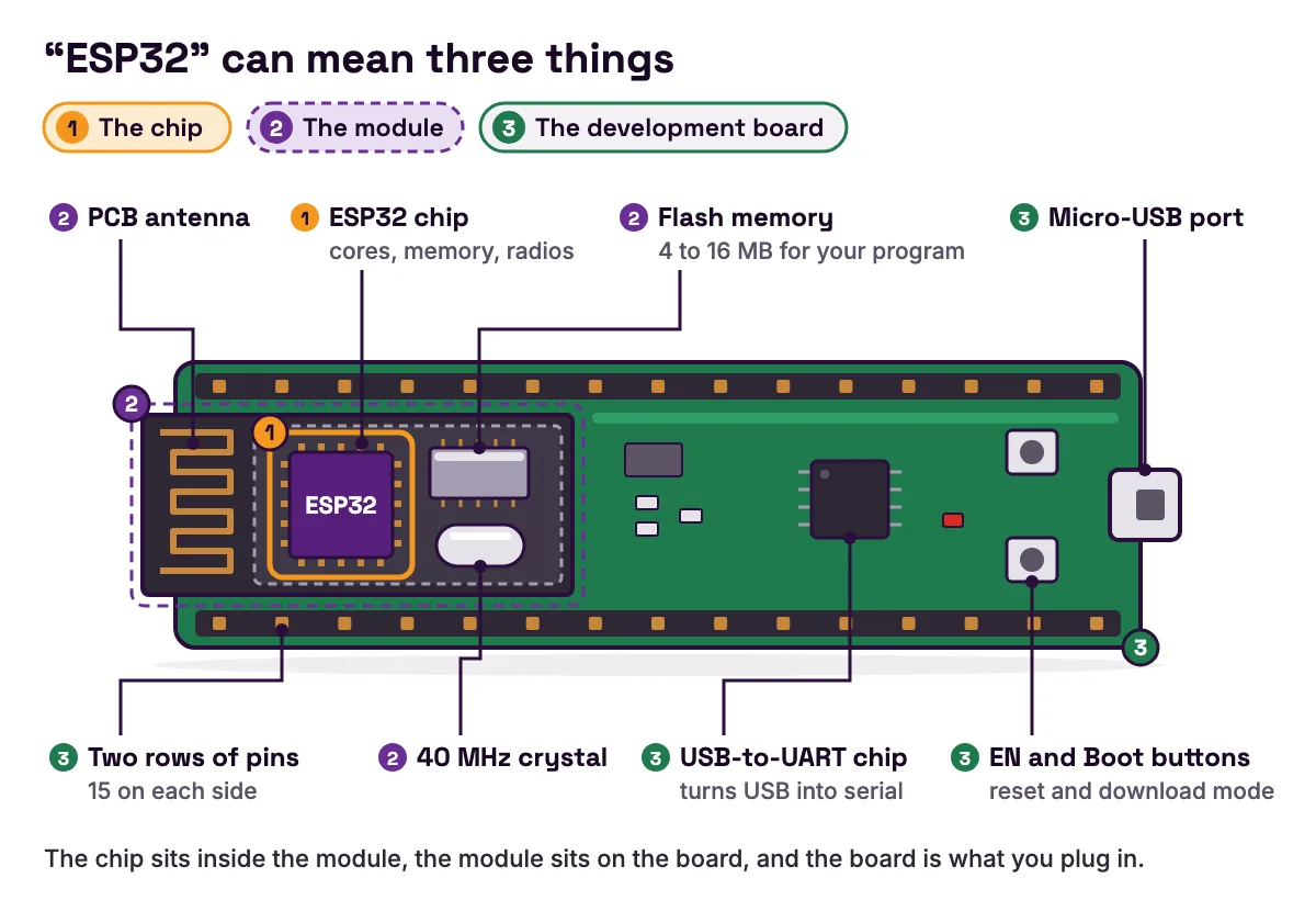
The MakerBuddy IoT Kit V1.0 carries a 30-pin ESP32 DevKit, and its parts and pins list explains that the DevKit turns the cable's 5 V into the 3.3 V the chip needs. Our guides to ESP32 development boards and what a microcontroller is go further.
What can an ESP32 do?
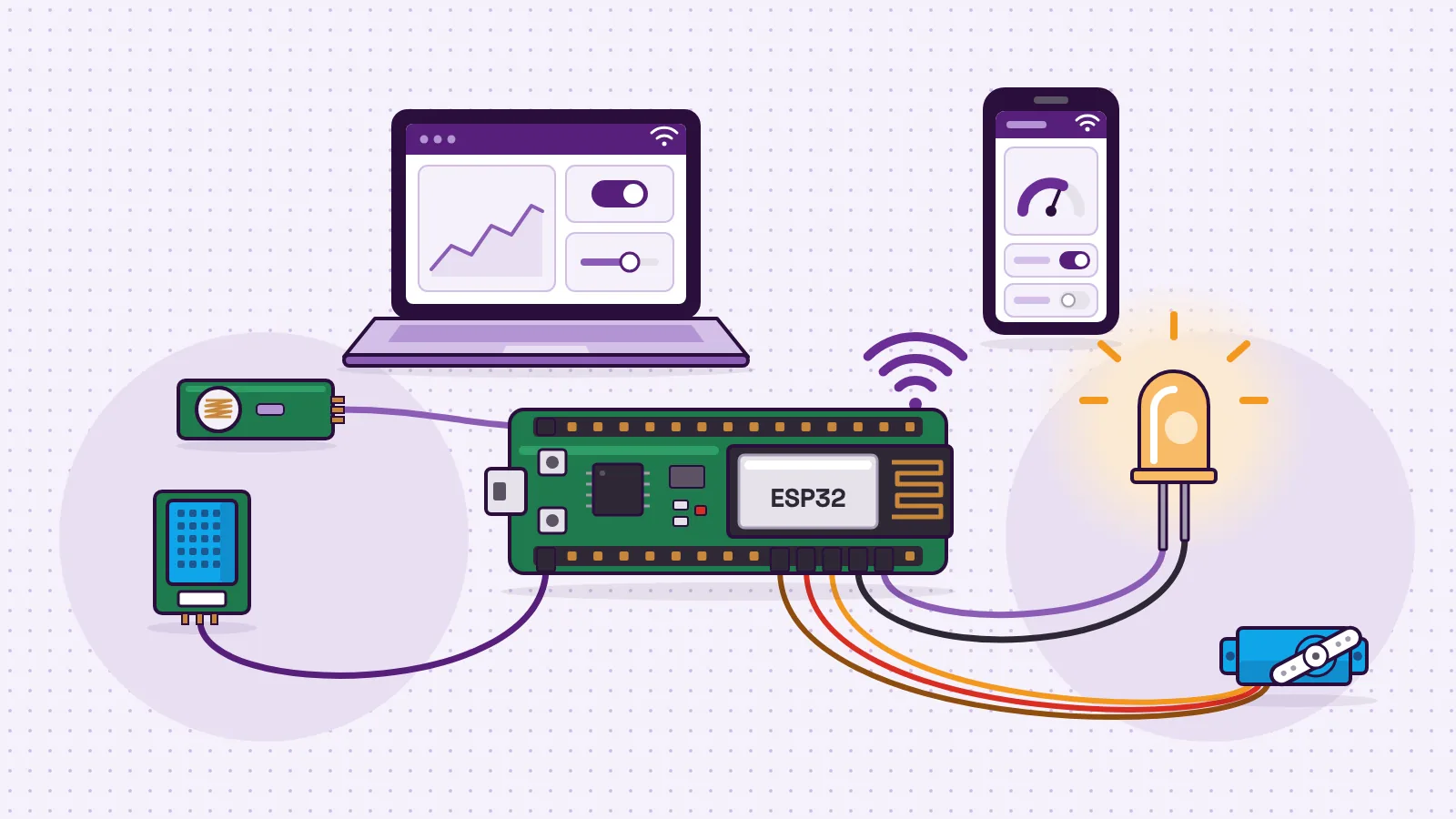
The ESP32 datasheet (opens in a new tab) lists the jobs Espressif designed it for, from smart homes and smart agriculture to robots, data loggers and cameras. For a student, they come down to four things.
- 1
Sense.
Read buttons, light, temperature, distance, motion, gas and soil moisture.
- 2
Decide.
Run a program or a rule: if the soil is dry, do something.
- 3
Act.
Dim a light, sound a buzzer, turn a servo, click a relay, write on a screen.
- 4
Connect.
Join Wi-Fi, so a phone or laptop can watch the readings and send commands.
The first three are the Input, Process, Output idea from Lesson 1 on electronics, automation and IoT. The fourth turns an automatic gadget into an IoT device. Our ESP32 and Arduino project ideas for students sorts builds by sensor and difficulty, and the visual guide to sensors explains the input side.
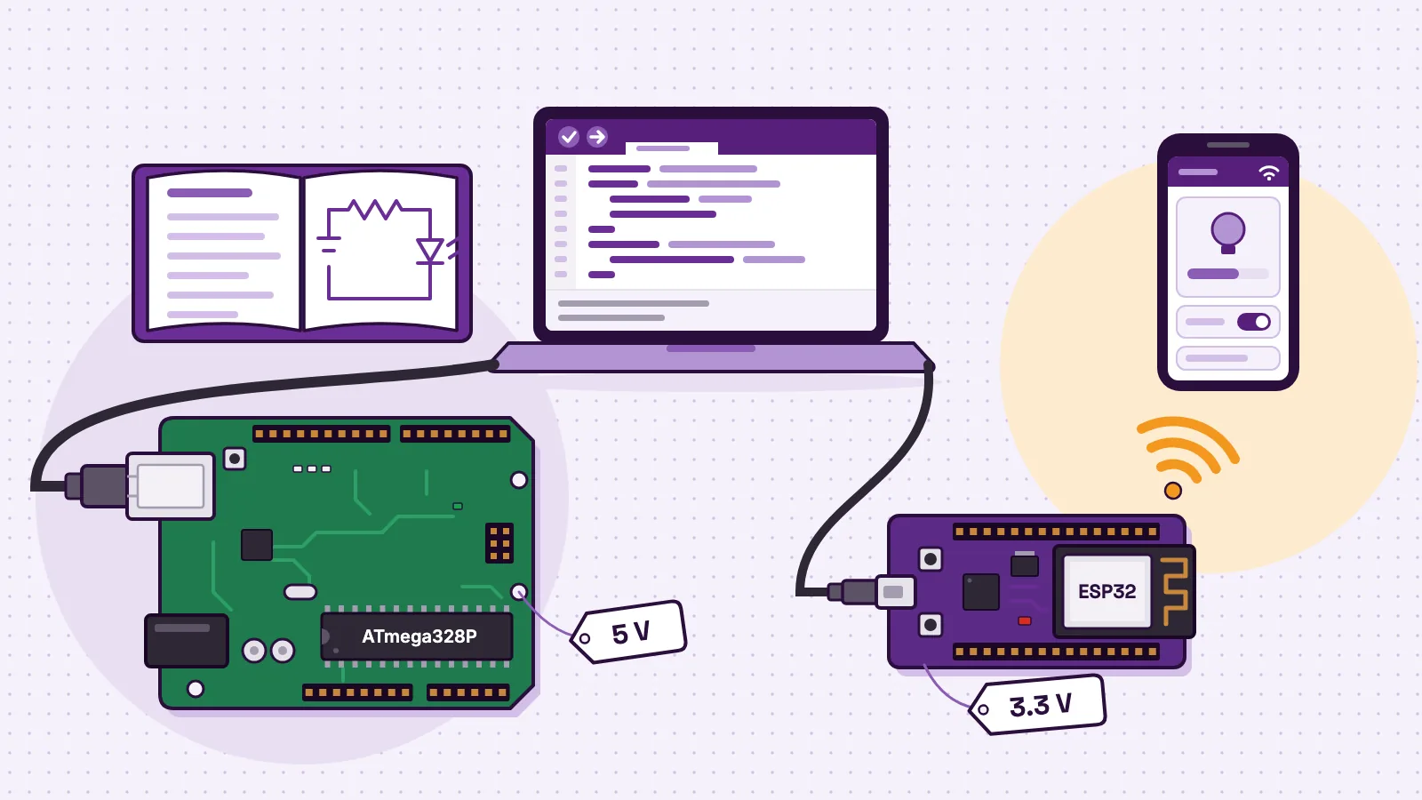
Two limits matter from day one. An ESP32 is not a desktop computer: it runs one program, with no desktop or apps. And its pins work at 3.3 V, not 5 V, which matters when you pick parts.
ESP32 vs Arduino Uno vs Raspberry Pi 5
These three boards solve different problems.
| ESP32 | Arduino UNO R3 | Raspberry Pi 5 | |
|---|---|---|---|
| What it is | Microcontroller with Wi-Fi | Microcontroller | Single-board computer |
| Processor | Xtensa LX6, 1 or 2 cores, up to 240 MHz | ATmega328P, 16 MHz | Quad-core 64-bit Arm Cortex-A76, 2.4 GHz |
| Working memory | 520 KB SRAM | 2 kB SRAM | 1 GB to 16 GB of RAM |
| Wireless | 2.4 GHz Wi-Fi and Bluetooth 4.2 | None on the board | Dual-band Wi-Fi and Bluetooth 5.0 |
| Pins for sensors | 34 GPIOs, up to 18 analog channels | 14 digital (6 PWM) and 6 analog | A 40-pin GPIO header |
| Logic level | 3.3 V | 5 V | 3.3 V |
| Runs | One program, from power-on | One sketch, from power-on | An operating system, Raspberry Pi OS |
| Best first use | Connected sensor projects | Simple 5 V circuits with no network | Projects that need a screen or a desktop |
- What it is
- ESP32
- Microcontroller with Wi-Fi
- Arduino UNO R3
- Microcontroller
- Raspberry Pi 5
- Single-board computer
- Processor
- ESP32
- Xtensa LX6, 1 or 2 cores, up to 240 MHz
- Arduino UNO R3
- ATmega328P, 16 MHz
- Raspberry Pi 5
- Quad-core 64-bit Arm Cortex-A76, 2.4 GHz
- Working memory
- ESP32
- 520 KB SRAM
- Arduino UNO R3
- 2 kB SRAM
- Raspberry Pi 5
- 1 GB to 16 GB of RAM
- Wireless
- ESP32
- 2.4 GHz Wi-Fi and Bluetooth 4.2
- Arduino UNO R3
- None on the board
- Raspberry Pi 5
- Dual-band Wi-Fi and Bluetooth 5.0
- Pins for sensors
- ESP32
- 34 GPIOs, up to 18 analog channels
- Arduino UNO R3
- 14 digital (6 PWM) and 6 analog
- Raspberry Pi 5
- A 40-pin GPIO header
- Logic level
- ESP32
- 3.3 V
- Arduino UNO R3
- 5 V
- Raspberry Pi 5
- 3.3 V
- Runs
- ESP32
- One program, from power-on
- Arduino UNO R3
- One sketch, from power-on
- Raspberry Pi 5
- An operating system, Raspberry Pi OS
- Best first use
- ESP32
- Connected sensor projects
- Arduino UNO R3
- Simple 5 V circuits with no network
- Raspberry Pi 5
- Projects that need a screen or a desktop
Sources: the ESP32 datasheet (opens in a new tab), the UNO R3 datasheet (opens in a new tab) and UNO Rev3 page (opens in a new tab), the Raspberry Pi 5 product page (opens in a new tab) and the Raspberry Pi GPIO documentation (opens in a new tab), which says its pins work at 3.3 V and must not be given 5 V.
Pick the UNO for simple 5 V circuits, a Raspberry Pi when you need a real computer, and the ESP32 when sensor readings should reach a phone or laptop. Our posts on ESP32 vs Arduino Uno for beginners and Arduino vs Raspberry Pi vs ESP32 go deeper.
ESP32 pins explained: GPIO, ADC1, ADC2 and the pins to avoid
GPIO means general-purpose input/output: a pin that can read a signal or send one. Espressif's GPIO reference (opens in a new tab) lists 34, numbered 0 to 39 with gaps. Five groups need care.
| Pin group | Pins | The rule |
|---|---|---|
| Flash pins | GPIO 6 to 11, and 16 to 17 on some modules | Usually wired to the flash and PSRAM inside the module. Leave them alone |
| Input-only pins | GPIO 34 to 39 | They read but never drive, and have no built-in pull-up or pull-down |
| Strapping pins | GPIO 0, 2, 5, 12 and 15 | Read by the chip at start-up. A part that holds one at the wrong level can stop the board starting |
| ADC1 pins | GPIO 32 to 39 | Analog inputs that keep working while Wi-Fi is on |
| ADC2 pins | GPIO 0, 2, 4, 12 to 15 and 25 to 27 | Analog inputs that cannot be used while Wi-Fi is on. As digital pins they are fine |
- Pin group
- Flash pins
- Pins
- GPIO 6 to 11, and 16 to 17 on some modules
- The rule
- Usually wired to the flash and PSRAM inside the module. Leave them alone
- Pin group
- Input-only pins
- Pins
- GPIO 34 to 39
- The rule
- They read but never drive, and have no built-in pull-up or pull-down
- Pin group
- Strapping pins
- Pins
- GPIO 0, 2, 5, 12 and 15
- The rule
- Read by the chip at start-up. A part that holds one at the wrong level can stop the board starting
- Pin group
- ADC1 pins
- Pins
- GPIO 32 to 39
- The rule
- Analog inputs that keep working while Wi-Fi is on
- Pin group
- ADC2 pins
- Pins
- GPIO 0, 2, 4, 12 to 15 and 25 to 27
- The rule
- Analog inputs that cannot be used while Wi-Fi is on. As digital pins they are fine
The ADC rule is the easiest to miss. Espressif's GPIO reference says it plainly: "ADC2 pins cannot be used when Wi-Fi is used." The MicroPython quick reference for the ESP32 (opens in a new tab) agrees: ADC block 1 sits on pins 32 to 39, and block 2 is also used by Wi-Fi.
Strapping pins have a job at start-up. The ESP32 datasheet (opens in a new tab) explains that GPIO 0 and 2 choose the boot mode and GPIO 12 sets the flash memory's voltage. The chip reads them at power-up or reset, then frees them as normal pins.
Our guides to which ESP32 pins are safe to use and the ESP32 ADC go pin by pin.
A tour of the ESP32 on the MakerBuddy board
Here is how one real board uses those pins. The MakerBuddy IoT Kit V1.0 has 6 parts built in and 9 parts that plug into labelled sockets. The table matches firmware 2.10 and the parts and pins list.
| Part | Built in or plug-in | GPIO | Signal | Pin group |
|---|---|---|---|---|
| Push button | Built in | 5 | Digital, pull-up | Strapping pin |
| Light sensor (LDR) | Built in | 35 | Analog, shown as 0 to 100 | ADC1, input only |
| Turning knob (potentiometer) | Built in | 34 | Analog, shown as 0 to 100 | ADC1, input only |
| Blue light | Built in | 12 | PWM brightness, 0 to 255 | Strapping pin |
| Colour light (RGB) | Built in | 13, 14, 27 | PWM, common anode | ADC2, as outputs |
| Buzzer | Built in | 4 | Digital, one tone | ADC2, as output |
| DHT11 temperature and humidity | Plug-in | 25 | Digital data | ADC2, digital use |
| DS18B20 waterproof probe | Plug-in | 26 | 1-Wire | ADC2, digital use |
| HC-SR04 distance sensor | Plug-in | Trigger 15, echo 2 | Timed pulses | Both strapping pins |
| HC-SR501 motion sensor | Plug-in | 18 | Digital | General pin |
| MQ-2 smoke and gas sensor | Plug-in | 33 | Analog, shown as 0 to 100 | ADC1 |
| Capacitive soil moisture sensor | Plug-in | 32 | Analog, calibrated | ADC1 |
| SG90 servo | Plug-in | 19 | PWM at 50 Hz, 0 to 180° | General pin |
| Relay | Plug-in | 23 | Digital, low-voltage loads only | General pin |
| 1602 text screen | Plug-in | SDA 21, SCL 22 | I2C at address 0x27 | General pins |
- Part
- Push button
- Built in or plug-in
- Built in
- GPIO
- 5
- Signal
- Digital, pull-up
- Pin group
- Strapping pin
- Part
- Light sensor (LDR)
- Built in or plug-in
- Built in
- GPIO
- 35
- Signal
- Analog, shown as 0 to 100
- Pin group
- ADC1, input only
- Part
- Turning knob (potentiometer)
- Built in or plug-in
- Built in
- GPIO
- 34
- Signal
- Analog, shown as 0 to 100
- Pin group
- ADC1, input only
- Part
- Blue light
- Built in or plug-in
- Built in
- GPIO
- 12
- Signal
- PWM brightness, 0 to 255
- Pin group
- Strapping pin
- Part
- Colour light (RGB)
- Built in or plug-in
- Built in
- GPIO
- 13, 14, 27
- Signal
- PWM, common anode
- Pin group
- ADC2, as outputs
- Part
- Buzzer
- Built in or plug-in
- Built in
- GPIO
- 4
- Signal
- Digital, one tone
- Pin group
- ADC2, as output
- Part
- DHT11 temperature and humidity
- Built in or plug-in
- Plug-in
- GPIO
- 25
- Signal
- Digital data
- Pin group
- ADC2, digital use
- Part
- DS18B20 waterproof probe
- Built in or plug-in
- Plug-in
- GPIO
- 26
- Signal
- 1-Wire
- Pin group
- ADC2, digital use
- Part
- HC-SR04 distance sensor
- Built in or plug-in
- Plug-in
- GPIO
- Trigger 15, echo 2
- Signal
- Timed pulses
- Pin group
- Both strapping pins
- Part
- HC-SR501 motion sensor
- Built in or plug-in
- Plug-in
- GPIO
- 18
- Signal
- Digital
- Pin group
- General pin
- Part
- MQ-2 smoke and gas sensor
- Built in or plug-in
- Plug-in
- GPIO
- 33
- Signal
- Analog, shown as 0 to 100
- Pin group
- ADC1
- Part
- Capacitive soil moisture sensor
- Built in or plug-in
- Plug-in
- GPIO
- 32
- Signal
- Analog, calibrated
- Pin group
- ADC1
- Part
- SG90 servo
- Built in or plug-in
- Plug-in
- GPIO
- 19
- Signal
- PWM at 50 Hz, 0 to 180°
- Pin group
- General pin
- Part
- Relay
- Built in or plug-in
- Plug-in
- GPIO
- 23
- Signal
- Digital, low-voltage loads only
- Pin group
- General pin
- Part
- 1602 text screen
- Built in or plug-in
- Plug-in
- GPIO
- SDA 21, SCL 22
- Signal
- I2C at address 0x27
- Pin group
- General pins
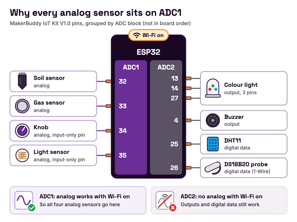
Why the analog sensors sit on ADC1 pins
The soil sensor (32), gas sensor (33), knob (34) and light sensor (35) all sit on ADC1. The board keeps its Wi-Fi on so dashboards can reach it, and Espressif's GPIO reference (opens in a new tab) says ADC2 pins cannot be used while Wi-Fi is. So every analog part had to go on ADC1.
Pins 34 and 35 are input-only, which suits a knob and a light sensor: they only send readings. The firmware reads each analog pin four times and averages the result, once a second. The ESP32 datasheet (opens in a new tab) suggests the same: take several samples and average them.
Why the outputs can sit on ADC2 pins
The colour light, the buzzer and the two temperature sensors need no analog reading, so Wi-Fi does not affect their ADC2 pins. Three parts use four of the five strapping pins: the button (5), the blue light (12) and the distance sensor (2 and 15). The board's pin notes say these pins affect how the ESP32 starts up, so check the board before you use them for anything else. Lesson 2's board tour walks students through every part and socket.
How to start ESP32 programming: four ways in
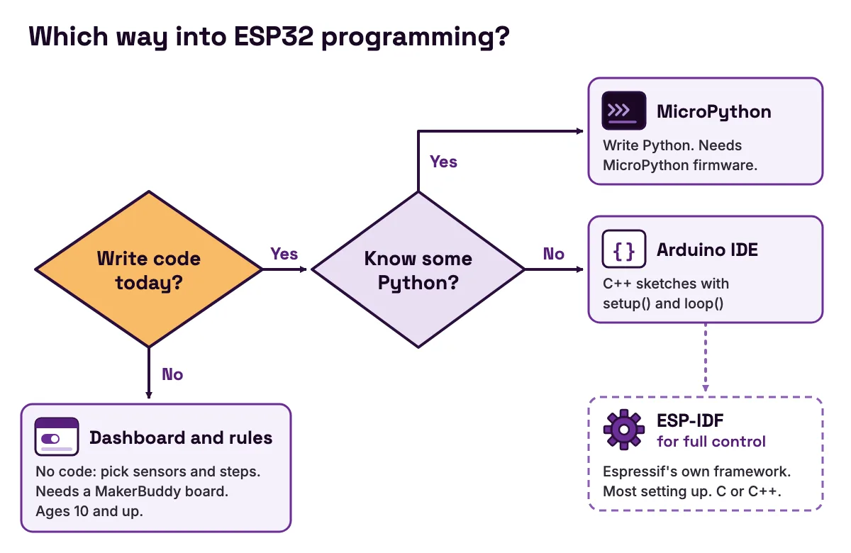
Pick the way into ESP32 programming that matches how much code you want to write today.
| Way in | What you write | What you need | Good for |
|---|---|---|---|
| MakerBuddy dashboard and rules | Nothing: you pick sensors, comparisons and steps | A browser and a MakerBuddy board | Ages 10 and up |
| Arduino IDE | C++ sketches with setup() and loop() | The free Arduino IDE and the esp32 package | Students ready to type their own code |
| MicroPython | Python | MicroPython firmware on the board | Students who know some Python |
| ESP-IDF | C or C++ on Espressif's own framework | The ESP-IDF tools, with VS Code or Espressif-IDE | Advanced students and professional projects |
- Way in
- MakerBuddy dashboard and rules
- What you write
- Nothing: you pick sensors, comparisons and steps
- What you need
- A browser and a MakerBuddy board
- Good for
- Ages 10 and up
- Way in
- Arduino IDE
- What you write
- C++ sketches with
setup()andloop() - What you need
- The free Arduino IDE and the esp32 package
- Good for
- Students ready to type their own code
- Way in
- MicroPython
- What you write
- Python
- What you need
- MicroPython firmware on the board
- Good for
- Students who know some Python
- Way in
- ESP-IDF
- What you write
- C or C++ on Espressif's own framework
- What you need
- The ESP-IDF tools, with VS Code or Espressif-IDE
- Good for
- Advanced students and professional projects
No code: the dashboard and rules
A MakerBuddy board arrives with its firmware installed. Lesson 3 on powering up and connectivity walks through setup.
- 1
Power the board from a 5 V USB charger or a computer.
- 2
A new board makes its own Wi-Fi network,
MakerBuddy_XXXX, with the password12345678. Join it from a laptop or phone. - 3
A setup page may open by itself. If it does not, go to
192.168.4.1in a browser. - 4
Type a device name, choose your 2.4 GHz Wi-Fi and its password, and press Save & Connect. The board restarts, joins your Wi-Fi and shows its IP address on the text screen, if one is plugged in.
Then open a dashboard: the free extension in Chrome, Edge or Firefox on a laptop, or Safari on a Mac, iPhone or iPad. Android phones cannot control the board yet. Choose your dashboard lists every option.
The dashboard shows live readings, switches outputs and builds rules that run on the board, up to 10 rules of up to 10 steps. There are no accounts, and readings stay on your network. The board's local connection has no password, so use only Wi-Fi you trust and never expose it to the internet. Our post on how no-code rules teach real logic shows what rules can do.
Arduino code, MicroPython and ESP-IDF
The Arduino IDE compiles a sketch and uploads it over USB. The Arduino CLI build notes (opens in a new tab) explain that .ino files are joined into one .cpp file and compiled with g++, so a sketch is C++ with helpers added.
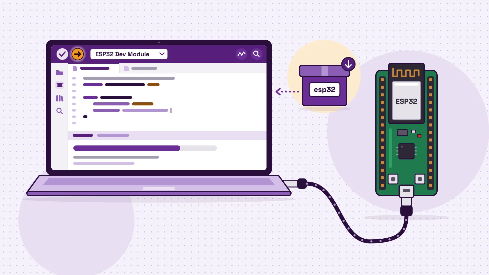
MicroPython is a small Python that runs on the chip. The MicroPython ESP32 quick reference (opens in a new tab) shows the style: Pin(0, Pin.OUT) makes an output pin, and adc.read_u16() reads an analog value from 0 to 65535. Our post on MicroPython vs Arduino C compares the two.
ESP-IDF is the Espressif IoT Development Framework. Its getting started guide (opens in a new tab) lists a toolchain, the CMake and Ninja build tools and the framework itself. It gives the most control and takes the most setting up.
ESP32 tutorial: your first Arduino sketch on the MakerBuddy board
This sketch uses only built-in parts, so there is no wiring. The knob dims the blue light, the button sounds the buzzer, and the Serial Monitor prints the readings.
Set up the Arduino IDE for ESP32
- 1
Install the free Arduino IDE.
- 2
In File > Preferences, paste the address below into "Additional Board Manager URLs". It comes from Espressif's Arduino-ESP32 install page (opens in a new tab).
- 3
Open Tools > Board > Boards Manager, search for "esp32" and install "esp32 by Espressif Systems", version 3.x.
- 4
Connect the board with a USB cable that carries data. Choose Tools > Board > ESP32 Dev Module, then the board's port under Tools > Port.
https://espressif.github.io/arduino-esp32/package_esp32_index.jsonThe Arduino development notes list the MakerBuddy firmware's own setup, and our guide to programming an ESP32 with the Arduino IDE goes step by step.
The sketch
// MakerBuddy first sketch: the knob dims the blue light, the button sounds the buzzer.
// Board: "ESP32 Dev Module" with "esp32 by Espressif Systems" 3.x.
// Uploading this sketch replaces the MakerBuddy firmware until you upload it again.

const int KNOB_PIN = 34;     // turning knob (potentiometer): ADC1, input only
const int LIGHT_PIN = 35;    // light sensor (LDR): ADC1, input only
const int BUTTON_PIN = 5;    // push button: reads LOW while pressed
const int LED_PIN = 12;      // blue light
const int BUZZER_PIN = 4;    // buzzer: one tone, on or off
const int RGB_PINS[] = {13, 14, 27};  // colour light: common anode

void setup() {
  Serial.begin(115200);

  pinMode(BUTTON_PIN, INPUT_PULLUP);
  pinMode(BUZZER_PIN, OUTPUT);
  digitalWrite(BUZZER_PIN, LOW);

  // Common anode: HIGH switches each colour off.
  for (int pin : RGB_PINS) {
    pinMode(pin, OUTPUT);
    digitalWrite(pin, HIGH);
  }

  // PWM on the blue light: 5000 Hz, 8-bit duty (0 to 255).
  if (!ledcAttach(LED_PIN, 5000, 8)) {
    Serial.println("PWM did not start on pin 12");
  }
}

void loop() {
  int knob = analogRead(KNOB_PIN);    // 0 to 4095
  int light = analogRead(LIGHT_PIN);  // 0 to 4095

  int brightness = map(knob, 0, 4095, 0, 255);
  ledcWrite(LED_PIN, brightness);

  bool pressed = digitalRead(BUTTON_PIN) == LOW;
  digitalWrite(BUZZER_PIN, pressed ? HIGH : LOW);

  Serial.printf("knob %4d  light %3d  brightness %3d  button %s\n",
                knob, map(light, 0, 4095, 0, 100), brightness,
                pressed ? "pressed" : "released");
  delay(200);
}
We compiled this sketch for ESP32 Dev Module with core 3.3.7, the one the MakerBuddy firmware is built with. Click Upload, then open the Serial Monitor at 115200 baud.
What each part does, and why
- 1
INPUT_PULLUPon the button.The chip holds the pin high and the button pulls it low, so pressed reads
LOW. The MakerBuddy firmware reads its button the same way. - 2
HIGHswitches the colour light off.It is a common-anode LED, so a high pin turns a colour off. These lines keep it dark while you test.
- 3
ledcAttach(LED_PIN, 5000, 8)sets up hardware PWM on pin 12: 5,000 pulses a second with 256 brightness steps. In Espressif's LEDC reference (opens in a new tab) it picks a channel for you, and
ledcWritethen takes the pin and the brightness. - 4
analogReadreturns 0 to 4095,the default 12-bit range in the ADC reference (opens in a new tab). Both readings come from ADC1 pins, so they would keep working if you added Wi-Fi.
- 5
map()rescales a number.0 to 4095 becomes 0 to 255 for brightness, and 0 to 100 for light, the same scale as the dashboard's Light Level card.
Turn the knob and the blue light fades. Hold the button and the buzzer sounds. Cover the light sensor and watch its number fall.
The same build with no code
The dashboard does the first half without code. Open the Potentiometer Mapping card and choose LED PWM: the firmware maps the knob's 0 to 4095 onto 0 to 255, the same sum as the sketch. After a restart the knob controls nothing again, so choose again. Lesson 4 on PWM dimming, Lesson 7 on light sensing and Lesson 9 on analog inputs and mapping teach these ideas one at a time.
Common ESP32 beginner mistakes, with fixes
The computer does not see the board
Symptom: No new port appears under Tools > Port. Cause: A charge-only USB cable with no data wires, or a missing driver. Espressif's Arduino-ESP32 troubleshooting page (opens in a new tab) lists both: some cables are only for charging, and the USB driver may be missing. Fix: Try a cable you know carries data and another USB port, then install the driver for your board's USB chip.
Upload stops with "Failed to connect"
Symptom: The upload fails while connecting. Cause: Espressif's esptool troubleshooting guide (opens in a new tab) says the chip is probably not entering its bootloader. Fix: Hold Boot, press and release EN, release Boot and upload again. Our guide to ESP32 boards that will not upload has more.
The board cannot find your Wi-Fi
Symptom: Your network is missing, or the board never joins. Cause: The ESP32 only uses 2.4 GHz, and for MakerBuddy, networks with a sign-in page or a username also fail, as the network notes explain. Fix: Use a 2.4 GHz network that needs only a name and a password, such as a phone hotspot. Our guide to ESP32 Wi-Fi explains why.
Analog readings stop once Wi-Fi starts
Symptom: A sensor reads fine until your sketch turns Wi-Fi on. Cause: It is on an ADC2 pin, and the GPIO reference (opens in a new tab) says ADC2 cannot be used while Wi-Fi is. Fix: Move it to an ADC1 pin, GPIO 32 to 39, as the MakerBuddy board does for all four analog parts.
Your code says ledcSetup was not declared
Symptom: A sketch from an older tutorial will not compile. Cause: Arduino-ESP32 3.0 merged ledcSetup and ledcAttachPin into ledcAttach, says Espressif's migration guide (opens in a new tab). Fix: Use ledcAttach(pin, frequency, resolution) and pass the pin, not a channel, to ledcWrite.
The board will not start after you wire a new part
Symptom: After you add a part, the board no longer starts or uploads. Cause: The part holds a strapping pin at the wrong level at start-up; the ESP32 datasheet (opens in a new tab) shows GPIO 0 and 2 choose the boot mode and GPIO 12 the flash voltage. Fix: Unplug the part, check the board starts, then move the part to a pin that is not a strapping pin, such as 18, 19 or 23 on a bare DevKit. On the MakerBuddy board those three already run the motion sensor, servo and relay.
When an ESP32 is not the right board
An ESP32 is a strong first board, but not for every project.
- Your parts need 5 V signals. The ESP32's pins top out at 3.6 V on a 3.3 V supply, by the datasheet's DC table (opens in a new tab). An Arduino UNO R3 (opens in a new tab) works at 5 V, so 5 V modules can connect to its pins directly.
- You need a screen, a keyboard or a full operating system. A Raspberry Pi 5 (opens in a new tab) runs an operating system, Raspberry Pi OS. An ESP32 runs one program.
- You need careful voltage measurements. The same datasheet (opens in a new tab) notes that at its widest input range (attenuation 3), readings above 3000, about 2450 mV, lose accuracy. A knob does not care. A science project measuring small voltage changes might.
- Your only Wi-Fi is 5 GHz. The ESP32 cannot see it. A phone hotspot set to 2.4 GHz is the usual way round this.
On a bare ESP32 you also wire and code every part before you see a single reading. For a class of ten-year-olds, that first hour can go on wiring rather than ideas.
Next steps: free lessons, project ideas and the kit
Lessons 1 to 3 follow the same order as this guide, and Lessons 4, 7 and 9 cover the blue light, light sensor and knob in the sketch. The full MakerBuddy curriculum has 32 free lessons for ages 10 and up, in 45 to 60 minute sessions across four terms, ending with a capstone in Lesson 31 and an expo in Lesson 32. The project ideas library adds 50 project ideas, 43 of them with no code.
If you want the board this guide tours, with its parts already on labelled sockets, you can order the MakerBuddy IoT kit. Pakistan orders online at PKR 40,000 per kit, and every other region gets a written quote. More ESP32 guides are on the MakerBuddy blog.
FAQ
What is the processing speed of the ESP32 chip?
The ESP32 runs at up to 240 MHz on one or two 32-bit cores. The ESP32 datasheet (opens in a new tab) notes that the single-core ESP32-S0WD tops out at 160 MHz. 240 MHz is fifteen times the 16 MHz of a classic Arduino UNO R3, according to the UNO R3 datasheet (opens in a new tab).
Can ChatGPT program an ESP32?
An AI chat tool can draft a sketch or a MicroPython script, but it cannot see your board or upload anything. A draft can use the wrong pins for your board, or old functions such as ledcSetup, which the Arduino-ESP32 3.0 migration guide (opens in a new tab) lists as removed. Check every pin, compile the code and test it before you trust it.
Is ESP32 or Arduino better for beginners?
For a project that uses Wi-Fi, the ESP32, because Wi-Fi and Bluetooth are built in. A classic Arduino UNO R3 is simpler and works at 5 V, but has no wireless. Both use the Arduino IDE, so what you learn on one carries over to the other.
Does ESP32 use C or C++?
Both. An Arduino sketch for the ESP32 is C++, compiled with g++, as the Arduino CLI build notes (opens in a new tab) explain. Espressif's own framework, ESP-IDF, is written in C and supports C++ programs (opens in a new tab) too. MicroPython lets you use Python instead.
Is ESP32 faster than Raspberry Pi?
No. A Raspberry Pi 5 (opens in a new tab) has four cores at 2.4 GHz and runs a full operating system, while the ESP32 has one or two cores at up to 240 MHz. The ESP32 wins on simplicity and power: its datasheet (opens in a new tab) rates its Deep-sleep mode at 10 µA.
Where is the ESP32 used?
Espressif's ESP32 datasheet (opens in a new tab) lists smart homes, industrial automation, health care, smart agriculture, robots, data loggers and cameras. In class, the MakerBuddy project ideas library uses it for builds such as a Mini Weather Station and a Plant Thirst Tracker, both with no code.
What is the difference between ESP32 and ESP32-WROOM?
The ESP32 is the chip. An ESP32-WROOM module is the small board that holds the chip with flash memory, a crystal and an antenna, as the ESP32-WROOM-32E datasheet (opens in a new tab) shows. A development board such as the ESP32-DevKitC carries a module and adds USB and pins.
Does an ESP32 need the internet to work?
No. An ESP32 runs its program with no network at all. A MakerBuddy board talks to its dashboard over your own Wi-Fi, with no accounts, and needs the internet only to open the web app or install a browser extension.
Sources
- Espressif: ESP32 Series Datasheet, version 5.3 (opens in a new tab)
- Espressif: ESP32-WROOM-32E and ESP32-WROOM-32UE datasheet (opens in a new tab)
- Espressif ESP-IDF: GPIO and RTC GPIO reference for the ESP32 (opens in a new tab)
- Espressif: ESP32-DevKitC V4 user guide (opens in a new tab)
- Espressif: Arduino-ESP32 getting started (opens in a new tab)
- Espressif: Installing Arduino-ESP32 (opens in a new tab)
- Espressif: Arduino-ESP32 ADC API reference (opens in a new tab)
- Espressif: Arduino-ESP32 LEDC API reference (opens in a new tab)
- Espressif: Arduino-ESP32 migration guide from 2.x to 3.0 (opens in a new tab)
- Espressif: ESP-IDF getting started for the ESP32 (opens in a new tab)
- Espressif: ESP-IDF C++ support (opens in a new tab)
- Espressif: esptool troubleshooting for the ESP32 (opens in a new tab)
- Espressif: Arduino-ESP32 troubleshooting (opens in a new tab)
- MicroPython: quick reference for the ESP32 (opens in a new tab)
- Arduino: UNO R3 datasheet (opens in a new tab)
- Arduino: UNO Rev3 product page (opens in a new tab)
- Arduino CLI: sketch build process (opens in a new tab)
- Raspberry Pi: Raspberry Pi 5 product page (opens in a new tab)
- Raspberry Pi: GPIO documentation for Raspberry Pi computers (opens in a new tab)