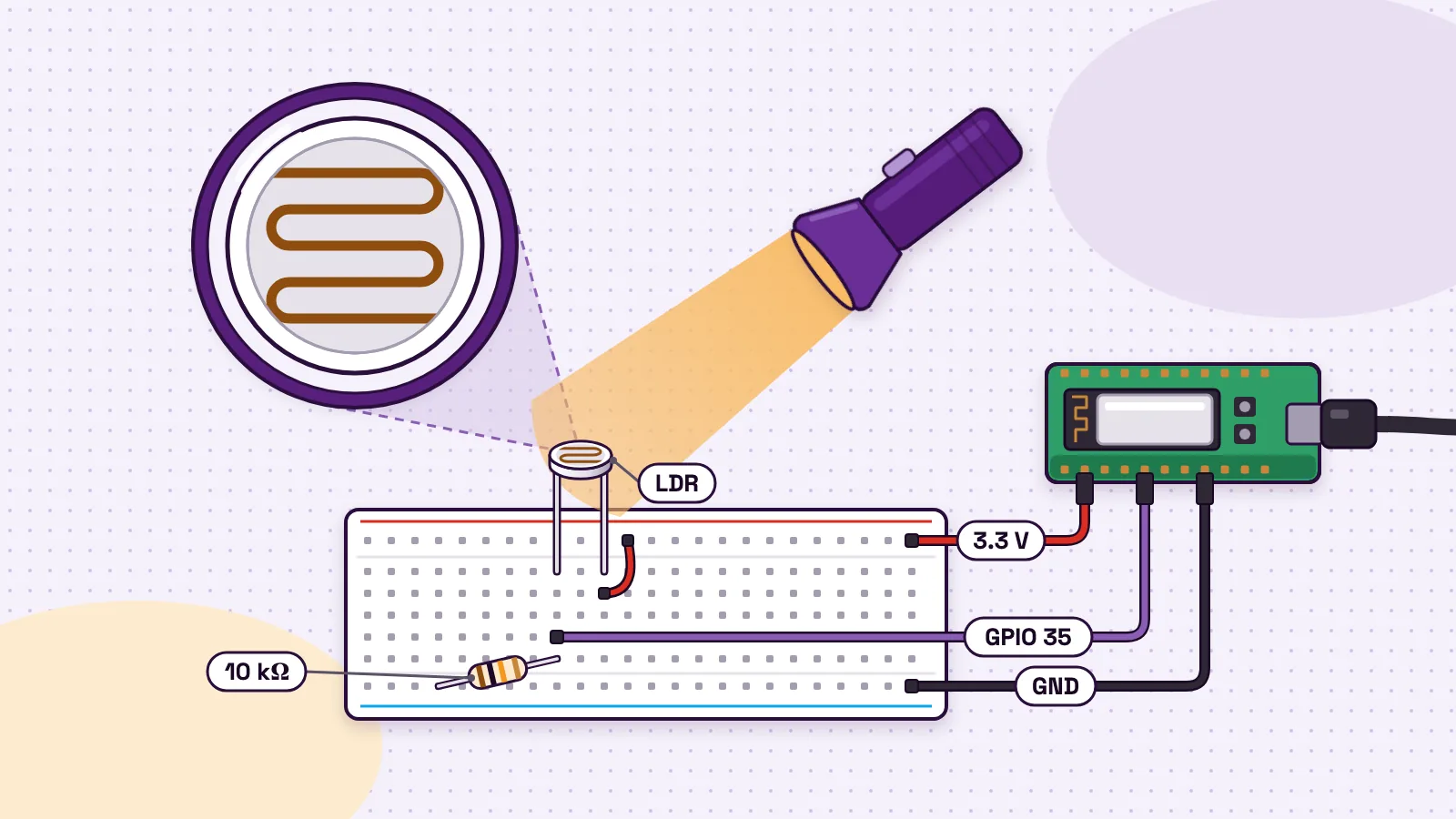
A light dependent resistor (LDR) is a resistor whose resistance changes with the light that falls on it. In the dark its resistance is high. In bright light it drops a long way. Adafruit's photocell tables (opens in a new tab) give one typical LDR about 600 kΩ in a dim hallway and about 100 Ω in full daylight. Put the LDR in a simple circuit and that change becomes a voltage a microcontroller can read. That is how night lights, dusk-to-dawn lamps and light-beam alarms know when to act.
You will also see it called a photoresistor, a photocell or a CdS cell. This guide explains how an LDR works, draws its resistance-vs-light graph, works through the LDR circuit with real numbers and lists where LDRs are used. The hands-on parts use the light sensor built into the MakerBuddy board, which Lesson 7, Light Sensing teaches with a Try it demo that runs in your browser.
What is an LDR? Meaning, other names and symbol
LDR stands for light dependent resistor. It is a passive part: it makes no electricity of its own, it only resists the current that flows through it. It has two legs and, like any resistor, no plus or minus side, so it works either way round.
Adafruit's photocell overview (opens in a new tab) describes the usual part as round and 5 mm across, with bigger ones up to 12 mm. It adds that they are often called CdS cells because they are made of cadmium sulphide. On top you can see a zig-zag track of that material between two metal contacts. Cadmium is toxic, as the World Health Organization's cadmium page (opens in a new tab) explains, so never cut or burn an old LDR; recycle it with other electronic waste.
In a circuit diagram, an LDR is a resistor, a small rectangle, with two arrows pointing at it. Oak National Academy's lesson on LDRs and thermistors (opens in a new tab) explains that the arrows stand for light shining on the component.
An LDR responds mostly to light you can see. The PDV-P8001 datasheet (opens in a new tab) gives a range of 400 to 700 nm, peaking at 520 nm, which is green. So an LDR reacts to brightness much as your eyes do; the RS datasheet (opens in a new tab) calls its cells' response similar to the human eye's.
How does a light dependent resistor work?
An LDR is made of a semiconductor. Oak National Academy's lesson (opens in a new tab) puts the idea simply: light gives electrons in the semiconductor the energy to move, as they do in a metal. In the dark, few electrons are free to carry current, so the resistance is high. As the light gets brighter, more electrons are freed and the resistance falls.
Real parts differ a lot. Here are three that are well documented.
| Part | Dark resistance | Resistance at 10 lux | Response at 10 lux |
|---|---|---|---|
| Adafruit shop photocell | About 200 kΩ | About 10 kΩ | Not given |
| Advanced Photonix PDV-P8001 | At least 0.2 MΩ | 3 to 11 kΩ | Rise time 55 ms, fall time 20 ms |
| NORP12, sold by RS | At least 1.0 MΩ | 9 kΩ typical | About 18 ms to react, 120 ms to recover |
- Part
- Adafruit shop photocell
- Dark resistance
- About 200 kΩ
- Resistance at 10 lux
- About 10 kΩ
- Response at 10 lux
- Not given
- Part
- Advanced Photonix PDV-P8001
- Dark resistance
- At least 0.2 MΩ
- Resistance at 10 lux
- 3 to 11 kΩ
- Response at 10 lux
- Rise time 55 ms, fall time 20 ms
- Part
- NORP12, sold by RS
- Dark resistance
- At least 1.0 MΩ
- Resistance at 10 lux
- 9 kΩ typical
- Response at 10 lux
- About 18 ms to react, 120 ms to recover
Figures from the Adafruit photocell overview (opens in a new tab), the PDV-P8001 datasheet (opens in a new tab) and the RS datasheet for the NORP12 (opens in a new tab).
What is 10 lux? Lux measures how much light lands on a surface. The RS datasheet (opens in a new tab) gives a rough guide: moonlight is about 0.1 lux, fluorescent lighting about 500 lux and bright sunlight about 30,000 lux. So 10 lux is a dim room.
An LDR is not instant either. The same datasheet shows the NORP12 reacting to light in about 18 ms at 10 lux but taking about 120 ms to recover when the light goes. For a night light that does not matter. For counting things that flash past, it does.
The LDR resistance-vs-light graph
The clearest way to see how an LDR behaves is to plot its resistance against the light level. Adafruit's guide to using a photocell (opens in a new tab) gives approximate values for one typical LDR:
| Light | Lux | LDR resistance |
|---|---|---|
| Dim hallway | 0.1 | 600 kΩ |
| Moonlit night | 1 | 70 kΩ |
| Dark room | 10 | 10 kΩ |
| Bright room or dark overcast day | 100 | 1.5 kΩ |
| Overcast day | 1,000 | 300 Ω |
| Full daylight | 10,000 | 100 Ω |
- Light
- Dim hallway
- Lux
- 0.1
- LDR resistance
- 600 kΩ
- Light
- Moonlit night
- Lux
- 1
- LDR resistance
- 70 kΩ
- Light
- Dark room
- Lux
- 10
- LDR resistance
- 10 kΩ
- Light
- Bright room or dark overcast day
- Lux
- 100
- LDR resistance
- 1.5 kΩ
- Light
- Overcast day
- Lux
- 1,000
- LDR resistance
- 300 Ω
- Light
- Full daylight
- Lux
- 10,000
- LDR resistance
- 100 Ω
Values are approximate, from the tables in Adafruit's Using a Photocell page (opens in a new tab).
Each time the light goes up ten times, the resistance falls, but not by ten times. From 1 to 10 lux it drops seven times, from 70 kΩ to 10 kΩ. From 1,000 to 10,000 lux it drops only three times, from 300 Ω to 100 Ω.
On ordinary graph paper the six points make a curve that plunges, then flattens into a long tail. With both axes counting in powers of ten, called log-log axes, they bend only gently and sit much closer to a straight line. The RS datasheet (opens in a new tab) draws its resistance graph this way, as a straight line. The PDV-P8001 datasheet (opens in a new tab) measures the slope between 10 and 100 lux and calls it sensitivity: 0.6 for that part. So for it, ten times more light makes the resistance 10 to the power of 0.6 times lower, which is about 4 times.
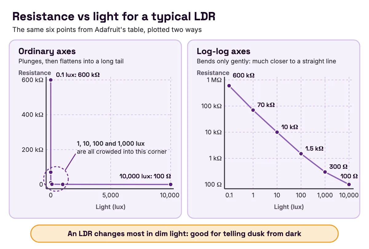
Two lessons come out of the graph. An LDR changes most in dim light, so it is good at telling dusk from dark. And the numbers are a guide, not a promise: Adafruit's overview (opens in a new tab) warns that photocells can vary by 50% or more. Always measure your own.
The LDR circuit: how a voltage divider turns light into a reading
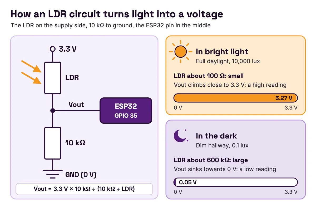
A microcontroller pin cannot measure resistance. It measures voltage. So you turn the LDR's resistance into a voltage with a voltage divider: the LDR and a fixed resistor in series between the supply and ground, with the pin connected to the point between them.
With the LDR on the supply side and the fixed resistor R on the ground side, Adafruit's guide (opens in a new tab) gives the middle voltage as:
Vout = Vcc × R ÷ (R + LDR)
In bright light the LDR's resistance is small, so Vout climbs close to the supply voltage. In the dark it is large, so Vout sinks towards 0 V. Swap the two parts round and the circuit works backwards: dark gives a high voltage. Both are correct, as long as you know which one you built.
GCSE physics calls this a potential divider, and Oak National Academy's lesson (opens in a new tab) describes using one to trigger a switch when it becomes too dark. The guide to the voltage divider formula and its sensor uses goes deeper.
Worked example: from lux to a 0–100 reading
Take a 3.3 V supply, the voltage the ESP32 datasheet (opens in a new tab) gives its characteristics at, and a 10 kΩ fixed resistor. On the ESP32, analogRead() turns a voltage into a whole number from 0 to 4095, according to Espressif's Arduino-ESP32 ADC reference (opens in a new tab). The MakerBuddy firmware then scales that to 0–100 with Arduino's map(), which drops any fraction.
The dark room row, worked through in full:
- 1
At 10 lux the LDR is about 10 kΩ.
- 2
Vout = 3.3 × 10,000 ÷ (10,000 + 10,000) = 1.65 V.
- 3
Ideal raw reading = 4095 × 1.65 ÷ 3.3 = 2047.5, which the converter gives as 2047.
- 4
Level = 2047 × 100 ÷ 4095 = 49.98, shown as 49.
The same sums for all six rows:
| Light | Lux | LDR | Voltage at the pin | Ideal raw reading | Level, 0 to 100 |
|---|---|---|---|---|---|
| Dim hallway | 0.1 | 600 kΩ | 0.05 V | 67 | 1 |
| Moonlit night | 1 | 70 kΩ | 0.41 V | 511 | 12 |
| Dark room | 10 | 10 kΩ | 1.65 V | 2047 | 49 |
| Bright room | 100 | 1.5 kΩ | 2.87 V | 3560 | 86 |
| Overcast day | 1,000 | 300 Ω | 3.20 V | 3975 | 97 |
| Full daylight | 10,000 | 100 Ω | 3.27 V | 4054 | 98 |
- Light
- Dim hallway
- Lux
- 0.1
- LDR
- 600 kΩ
- Voltage at the pin
- 0.05 V
- Ideal raw reading
- 67
- Level, 0 to 100
- 1
- Light
- Moonlit night
- Lux
- 1
- LDR
- 70 kΩ
- Voltage at the pin
- 0.41 V
- Ideal raw reading
- 511
- Level, 0 to 100
- 12
- Light
- Dark room
- Lux
- 10
- LDR
- 10 kΩ
- Voltage at the pin
- 1.65 V
- Ideal raw reading
- 2047
- Level, 0 to 100
- 49
- Light
- Bright room
- Lux
- 100
- LDR
- 1.5 kΩ
- Voltage at the pin
- 2.87 V
- Ideal raw reading
- 3560
- Level, 0 to 100
- 86
- Light
- Overcast day
- Lux
- 1,000
- LDR
- 300 Ω
- Voltage at the pin
- 3.20 V
- Ideal raw reading
- 3975
- Level, 0 to 100
- 97
- Light
- Full daylight
- Lux
- 10,000
- LDR
- 100 Ω
- Voltage at the pin
- 3.27 V
- Ideal raw reading
- 4054
- Level, 0 to 100
- 98
LDR values are Adafruit's approximate figures from Using a Photocell (opens in a new tab); the rest is calculated for a perfect converter.
The table teaches three things. First, the reading is not lux. Light rises 100 times from the hallway to the dark room and the level climbs from 1 to 49. It rises another 100 times from the bright room to full daylight and the level only creeps from 86 to 98. With 10 kΩ, this circuit is most sensitive in dim light.
Second, a real converter is less tidy. Espressif's ADC reference (opens in a new tab) gives the classic ESP32's widest measurable range as 150 mV to 3100 mV. The 0.05 V, 3.20 V and 3.27 V rows sit outside it, so expect them at or near the ends of the scale. That is why two very bright lights can both read 100 in Lesson 7.
Third, the fixed resistor sets where the circuit is sensitive. Adafruit's guide (opens in a new tab) warns that 10 kΩ quickly saturates in a bright place, and gives a rule credited to Axel Benz: measure the LDR's lowest and highest resistance in the light you care about, then use R = √(Rmin × Rmax). To tell a moonlit night (70 kΩ) from an overcast day (300 Ω): √(70,000 × 300) = √21,000,000, about 4,583 Ω. A standard 4.7 kΩ resistor fits.
The MakerBuddy board has its own LDR and fixed resistor, so its numbers will not match this table. The guide to reading analog sensors accurately with the ESP32 ADC covers the converter in more depth.
The LDR sensor on the MakerBuddy board
The MakerBuddy IoT Kit V1.0 has an LDR built into the board, next to the label 35-LDR, already wired in its own voltage divider. The board comes in purple or green, and both colours are the same board. The visual guide to the types of sensors used in student projects shows where the LDR fits among the kit's nine sensors, and more sensor guides are on the MakerBuddy blog.
The LDR is read on GPIO 35, and that pin choice matters. Espressif's GPIO reference (opens in a new tab) lists GPIO 35 as an ADC1 channel and states that ADC2 pins cannot be used when Wi-Fi is used. Because the LDR is on ADC1, the board can read it while it talks to your dashboard.
Once a second, the firmware takes four readings, averages them to smooth out noise and scales the result to 0–100. Low means dark and high means bright. The dashboard's Light Level card shows that number and updates about every 2 seconds. The technical details page lists the pin with every other part.
The light level can feed four things:
- The Light Level card, for watching and recording readings.
- Rules, where Light Level (LDR) is one of the sensors a rule can test.
- The text screen, where the
{light}wildcard puts the live level into custom text such asLight: {light}. - The Servo Mapping card: choose Light level and the servo turns from 0° at level 0 to 180° at level 100, or the other way with Invert direction, a start for a model window blind.
In Lesson 7, students cover the LDR, shade it and shine a torch on it, fill a five-row data table, then choose thresholds for classroom lights, security lights and a nightlight. The lesson's Try it demo runs the same activity on a simulated board in your browser, including a quick cover that the dashboard can miss. Lesson 9, Analog Inputs, then uses the same 0–100 idea with the turning knob.
Build an LDR night light step by step (no code)
This build turns the board's blue light on when the room gets dark and off when it gets bright again. You need the board, USB power, 2.4 GHz Wi-Fi (a phone hotspot works) and a laptop, iPhone or iPad with the dashboard open. Android phones cannot control the board yet; choosing your dashboard explains the options.
Step 1: measure your room
Open the Light Level card. Write down three numbers: the LDR fully covered, under a hand shadow and in normal room light. Say you get 6, 20 and 55. These are example numbers; yours will differ.
Step 2: choose two thresholds with a gap
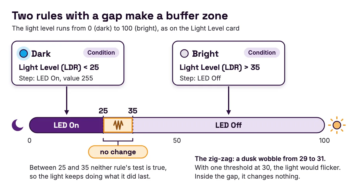
If the light turns on below 30 and off above 30, a reading that wobbles between 29 and 31 at dusk makes it flicker. Use two numbers instead: on below 25, off above 35. Lesson 7's bonus challenge suggests exactly this buffer zone. It is called hysteresis, and the guide to why a fan keeps switching on and off explains it in full.
Step 3: make the Dark rule
- 1
Open the Rule Engine tab and type
Darkas the Rule Name. - 2
Choose the Condition loop mode.
- 3
Set Sensor to Light Level (LDR), Operator to Less than (<) and Threshold to 25.
- 4
Add Step: LED On, Value 255 for full brightness, Delay (ms) 1000.
- 5
Click Save Rule.
Step 4: make the Bright rule
- 1
Type
Brightas the Rule Name and choose the Condition loop mode. - 2
Set Sensor to Light Level (LDR), Operator to Greater than (>) and Threshold to 35.
- 3
Add Step: LED Off, Delay (ms) 1000.
- 4
Click Save Rule.
Step 5: test it
Cover the LDR with your hand. About a second later the blue light comes on, because a rule waits until its test has held for 0.3 seconds and the board reads the sensor once a second. Take your hand away and the light goes off. Now hold your hand so the level sits between 25 and 35. Nothing changes: the light keeps doing what it did last. That is the gap working.
Why two rules? A Condition rule repeats its steps while its test is true. When the test turns false, it finishes its current round and stops, without undoing anything. So LED On stays on until the Bright rule runs LED Off. The automation rules documentation lists these timings. Lesson 26, Sensor-Based Control, and Lesson 27, Range Logic, build rules like these, and the guide to if-then statements with real sensors explains the logic.
Rules run on the board, not in your browser, so the night light keeps working after you close the dashboard. The board has no clock, so it cannot switch on at 7 pm. It switches on when it gets dark, which is how a dusk-to-dawn lamp works too.
The MakerBuddy project idea library has more LDR builds, such as the Dusk Lamp, where the relay switches a small low-voltage lamp (never mains), and the Shadow Detector, where the buzzer beeps when a shadow passes. The coming automatic night light and street light project with an LDR turns the night light into a full build.
Read an LDR with Arduino code on the ESP32
This sketch is the night light in code. It reads the LDR on GPIO 35, prints the raw number, the voltage and the 0–100 level once a second, and switches the blue light on GPIO 12 with the same 25 and 35 gap. Use the "esp32 by Espressif Systems" boards package, version 3.x, the ESP32 Dev Module board and a Serial Monitor at 115200 baud.
// MakerBuddy board (ESP32 Dev Module): an LDR night light with a gap between on and off.
// Uploading this replaces the MakerBuddy firmware until you upload that again.

const int LDR_PIN = 35;    // built-in light sensor, analog input on ADC1
const int LED_PIN = 12;    // built-in blue light

const int ON_BELOW = 25;   // turn the light on when the level drops below this
const int OFF_ABOVE = 35;  // turn it off only when the level rises above this

bool lightOn = false;

// Average four reads, like the MakerBuddy firmware, to smooth out noise.
int readAverage(int pin) {
  long sum = 0;
  for (int i = 0; i < 4; i++) {
    sum += analogRead(pin);  // 0 to 4095 on the ESP32 (12-bit)
  }
  return sum / 4;
}

void setup() {
  Serial.begin(115200);      // match the Serial Monitor speed
  pinMode(LED_PIN, OUTPUT);
  digitalWrite(LED_PIN, LOW);
}

void loop() {
  int raw = readAverage(LDR_PIN);
  int level = map(raw, 0, 4095, 0, 100);           // same 0-100 scale as the Light Level card
  int millivolts = analogReadMilliVolts(LDR_PIN);  // the voltage at the pin, in mV

  if (!lightOn && level < ON_BELOW) {
    lightOn = true;                                // dark enough: switch on
  } else if (lightOn && level > OFF_ABOVE) {
    lightOn = false;                               // bright enough: switch off
  }
  digitalWrite(LED_PIN, lightOn ? HIGH : LOW);

  Serial.printf("raw %4d   %4d mV   level %3d   light %s\n",
                raw, millivolts, level, lightOn ? "ON" : "off");
  delay(1000);  // once a second, the same pace as the MakerBuddy firmware
}
What each part does:
- 1
readAverage()takes four analog reads and averages them, as the MakerBuddy firmware does. - 2
map()turns 0–4095 into 0–100, so your numbers match the Light Level card and your Lesson 7 table. - 3
analogReadMilliVolts()returns the pin's voltage as a calibrated value in millivolts, according to Espressif's ADC reference (opens in a new tab). Compare it with the worked example. - 4
The two
iftests make the gap. Between 25 and 35,lightOnkeeps its last value.
Open the Serial Monitor and cover the LDR. All three numbers fall, and the blue light comes on once the level drops below 25. When you finish, put the MakerBuddy firmware back with the steps in install by USB.
Where LDRs are used in real life
What is an LDR used for? Anything that has to notice light or dark, cheaply and simply.
| Where it is used | What the LDR notices | What happens next |
|---|---|---|
| Night lights and dusk-to-dawn lamps | It is getting dark | A lamp turns on |
| Camera exposure and shutter control | How bright the scene is | The camera sets how long to let light in |
| Counting items on a production line | Each item blocks a beam of light | A counter goes up by one |
| Burglar alarms and break-beam sensors | Someone breaks a beam | An alarm sounds |
| Smoke detection | Less light gets through the air | A warning goes off |
| Presence detection | A shadow falls on the sensor | A light or display wakes up |
- Where it is used
- Night lights and dusk-to-dawn lamps
- What the LDR notices
- It is getting dark
- What happens next
- A lamp turns on
- Where it is used
- Camera exposure and shutter control
- What the LDR notices
- How bright the scene is
- What happens next
- The camera sets how long to let light in
- Where it is used
- Counting items on a production line
- What the LDR notices
- Each item blocks a beam of light
- What happens next
- A counter goes up by one
- Where it is used
- Burglar alarms and break-beam sensors
- What the LDR notices
- Someone breaks a beam
- What happens next
- An alarm sounds
- Where it is used
- Smoke detection
- What the LDR notices
- Less light gets through the air
- What happens next
- A warning goes off
- Where it is used
- Presence detection
- What the LDR notices
- A shadow falls on the sensor
- What happens next
- A light or display wakes up
The PDV-P8001 datasheet (opens in a new tab) lists night light controls, camera exposure and shutter controls. The RS LDR datasheet (opens in a new tab) lists smoke detection, automatic lighting control, batch counting and burglar alarm systems. Adafruit's photocell overview (opens in a new tab) adds presence detection and break-beam sensing.
Phones and laptops that dim their screens sense light too, but that job suits other parts. Vishay's TEPT4400 datasheet (opens in a new tab), for a phototransistor, lists display backlight dimming and keypad backlighting in mobile devices among its uses, and also "replacement of CdS photoresistors".
LDR vs photodiode, phototransistor and digital light sensors
An LDR is one of four common ways to sense light. This table uses one well-documented part for each.
| Sensor | What light changes | A figure from its datasheet | Can it report lux? | Good for |
|---|---|---|---|---|
| LDR (NORP12) | Its resistance | About 120 ms to recover at 10 lux | No, cells vary too much | Light or dark decisions, first projects |
| Photodiode (Vishay BPW34) | A tiny current | 100 ns rise and fall time | Only after calibration | Fast light beams and signals |
| Phototransistor (Vishay TEPT4400) | A larger current | 200 µA at 100 lux, peak at 570 nm | Only after calibration | Screen dimming, replacing CdS cells |
| Digital light sensor (BH1750 board) | A number sent over I2C | 16-bit readings from 0 to 65K+ lux | Yes | Measuring light in experiments |
- Sensor
- LDR (NORP12)
- What light changes
- Its resistance
- A figure from its datasheet
- About 120 ms to recover at 10 lux
- Can it report lux?
- No, cells vary too much
- Good for
- Light or dark decisions, first projects
- Sensor
- Photodiode (Vishay BPW34)
- What light changes
- A tiny current
- A figure from its datasheet
- 100 ns rise and fall time
- Can it report lux?
- Only after calibration
- Good for
- Fast light beams and signals
- Sensor
- Phototransistor (Vishay TEPT4400)
- What light changes
- A larger current
- A figure from its datasheet
- 200 µA at 100 lux, peak at 570 nm
- Can it report lux?
- Only after calibration
- Good for
- Screen dimming, replacing CdS cells
- Sensor
- Digital light sensor (BH1750 board)
- What light changes
- A number sent over I2C
- A figure from its datasheet
- 16-bit readings from 0 to 65K+ lux
- Can it report lux?
- Yes
- Good for
- Measuring light in experiments
Figures from the RS datasheet for the NORP12 (opens in a new tab), Vishay's BPW34 datasheet (opens in a new tab) and TEPT4400 datasheet (opens in a new tab), and Adafruit's BH1750 product page (opens in a new tab).
The LDR wins on simplicity: Adafruit's overview (opens in a new tab) calls photocells small, inexpensive, low-power and easy to use, which makes the LDR a good first light sensor for a classroom. It loses on precision and speed. The same page says photocells should not be used to find precise light levels in lux, so a science-fair experiment that measures light needs a calibrated digital sensor, and very quick flashes need a photodiode. The guide to photoresistors vs light sensor modules compares the ready-made boards sold as "LDR sensor modules".
Common LDR mistakes and how to fix them
Each mistake below has a symptom you can see, the cause behind it and the fix.
The night light flickers on and off at dusk
- Symptom: as the room darkens, the light blinks on and off every second or two.
- Cause: there is one threshold, and the reading wobbles either side of it.
- Fix: use two thresholds with a gap, such as on below 25 and off above 35.
The lamp switches itself off as soon as it comes on
- Symptom: the light comes on, goes off a second later, then comes on again.
- Cause: the lamp's own light reaches the LDR and lifts the reading above the off threshold.
- Fix: point the lamp away from the sensor or shade the sensor, then test with the lamp in its final position.
The reading is stuck near 0 or near 100
- Symptom: in your own circuit, the number hardly moves whatever you do.
- Cause: the fixed resistor does not suit your light. Adafruit's guide (opens in a new tab) warns that 10 kΩ quickly saturates in a bright place.
- Fix: measure the LDR in your darkest and brightest light, then pick R = √(Rmin × Rmax). If dark reads high instead, the LDR and resistor are swapped.
The reading goes wrong when Wi-Fi connects
- Symptom: your own sketch reads the LDR fine until it joins Wi-Fi.
- Cause: the LDR is on an ADC2 pin, and Espressif's GPIO reference (opens in a new tab) says ADC2 pins cannot be used when Wi-Fi is used.
- Fix: move it to an ADC1 pin. All of MakerBuddy's analog sensors use ADC1 pins, which is why GPIO 35 keeps working on Wi-Fi.
Two boards give different numbers under the same light
- Symptom: two MakerBuddy boards side by side show different light levels.
- Cause: LDRs vary from part to part, by 50% or more according to Adafruit's overview (opens in a new tab).
- Fix: measure each board and set its thresholds from its own table.
FAQ
What is an LDR used for?
An LDR is used wherever a device must notice light or dark: night lights, automatic lighting, camera exposure, burglar alarms, smoke detection and counting objects that break a beam of light. In student projects it runs night lights, shadow alarms and dusk lamps.
What does LDR stand for?
LDR stands for light dependent resistor. It is also called a photoresistor, a photocell or a CdS cell, after the cadmium sulphide it is made from. All four names mean the same part.
Is an LDR analog or digital?
An LDR is analog. Its resistance changes smoothly with light, so the voltage in its circuit can take any value in a range. A microcontroller reads it on an analog pin, such as GPIO 35 on the MakerBuddy board. Even when an LDR sits on a ready-made module, the LDR itself is still analog.
What is the difference between an LED and an LDR?
An LED makes light; an LDR senses it. An LED is an output that glows when current flows, and it only works one way round. An LDR is an input whose resistance changes with light, and it works either way round. A night light uses both.
How does an LDR work in GCSE physics?
GCSE physics teaches that an LDR's resistance falls as the light gets brighter. Placed in a potential divider, it makes a voltage that changes with light, which can switch on a lamp when it gets dark. Oak National Academy's lesson on LDRs and thermistors (opens in a new tab) covers the same ideas.
How fast does an LDR respond to light?
In tens of milliseconds, and it recovers in the dark more slowly than it reacts to light. The RS datasheet for the NORP12 (opens in a new tab) gives about 18 ms to react and 120 ms to recover at 10 lux. That is fast enough for lights and alarms, but too slow for fast flickering light.
Can an LDR measure light in lux?
Not accurately. Cells vary a lot, and resistance does not fall in a straight line with light. Adafruit's overview (opens in a new tab) advises against using photocells for precise light levels in lux. For lux, use a calibrated digital light sensor such as the BH1750.
Do I need a kit to learn how an LDR works?
No. The Try it demo in Lesson 7 runs in your browser on a simulated board. A real kit lets you measure your own room and build rules that react to it. The MakerBuddy kit has an LDR built into the board alongside its other sensors; Pakistan orders are placed online and other countries get a written quote on the MakerBuddy kit order page.
Sources
- Adafruit, Photocells overview (opens in a new tab): 200 kΩ dark to 10 kΩ at 10 lux, 5 mm round cells up to 12 mm, CdS construction, variation of 50% or more, not for precise lux, good for presence and break-beam sensing.
- Adafruit, Using a Photocell (opens in a new tab): voltage divider formula, approximate resistance from 0.1 to 10,000 lux, 10 kΩ saturating in bright light, the Axel Benz √(Rmin × Rmax) rule.
- Advanced Photonix, PDV-P8001 CdS photocell datasheet (Adafruit copy) (opens in a new tab): dark resistance, 3 to 11 kΩ at 10 lux, 400 to 700 nm with a 520 nm peak, sensitivity 0.6, rise and fall times, night light and camera uses.
- RS Components, Light dependent resistors datasheet for the NORP12 and NSL19-M51 (Components101 copy) (opens in a new tab): resistance at 10 lux, dark resistance, rise and fall times, typical lux of common light sources, a response similar to the human eye, a log-log resistance graph, applications.
- World Health Organization, Cadmium (opens in a new tab): cadmium's toxic effects and the risk from disposing of and recycling electronic waste.
- Oak National Academy, LDRs and thermistors (opens in a new tab): resistance falls as light brightens, the semiconductor explanation, the circuit symbol, a potential divider that switches when it gets dark.
- Espressif, ESP32 datasheet (opens in a new tab): electrical characteristics given at 3.3 V.
- Espressif, Arduino-ESP32 ADC API reference (opens in a new tab): 12-bit readings from 0 to 4095, 150 mV to 3100 mV measurable range at 11 dB on the ESP32, calibrated
analogReadMilliVolts(). - Espressif, ESP-IDF GPIO and RTC GPIO reference for the ESP32 (opens in a new tab): GPIO 35 is ADC1 channel 7, ADC2 pins cannot be used when Wi-Fi is used.
- Vishay, BPW34 silicon PIN photodiode datasheet (opens in a new tab): 100 ns rise and fall time.
- Vishay, TEPT4400 ambient light sensor datasheet (opens in a new tab): phototransistor, 200 µA at 100 lux, 570 nm peak, backlight dimming and replacement of CdS photoresistors.
- Adafruit, BH1750 light sensor product page (opens in a new tab): 16-bit readings in lux, 0 to 65K+ lux, I2C connectors.