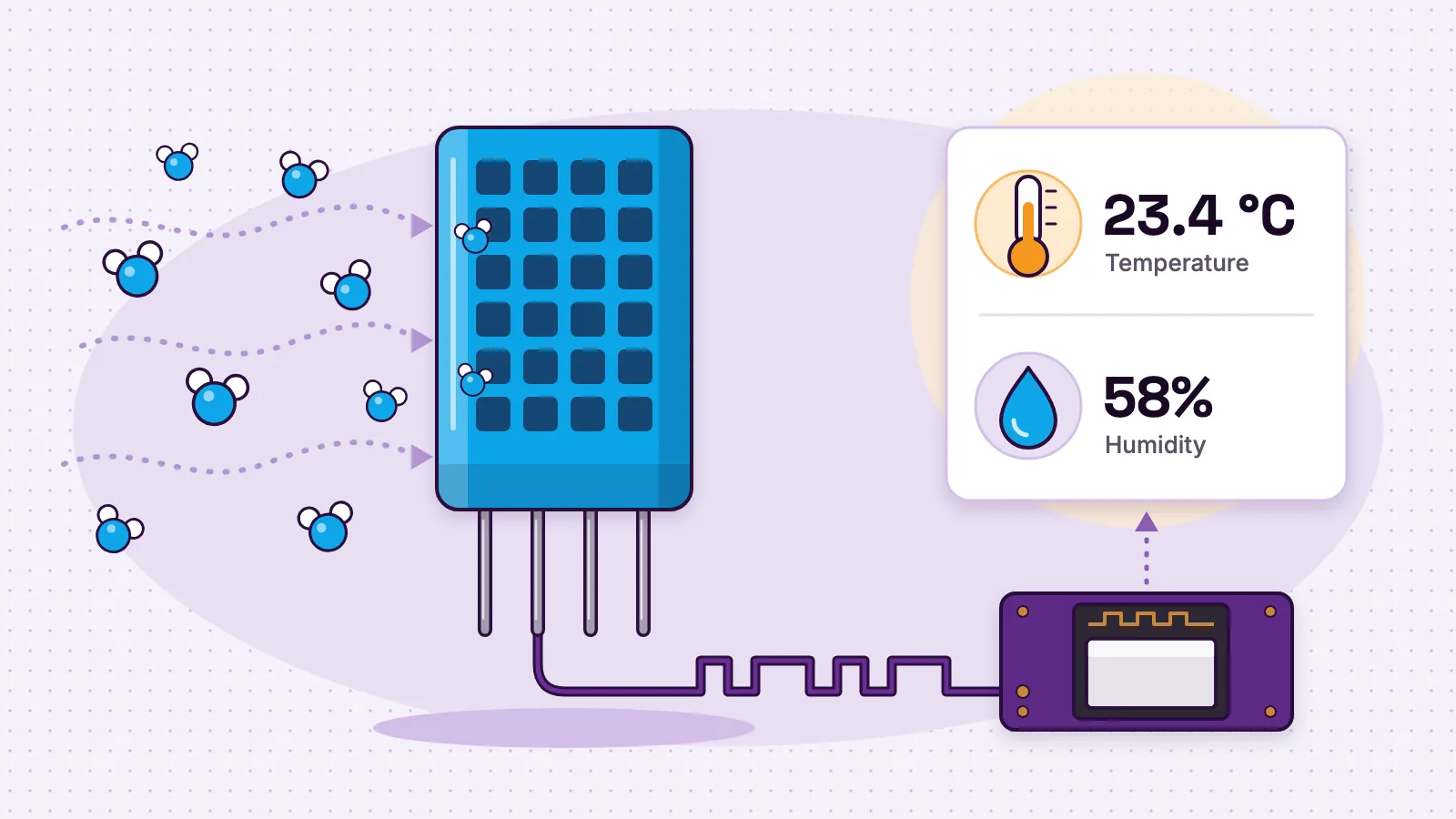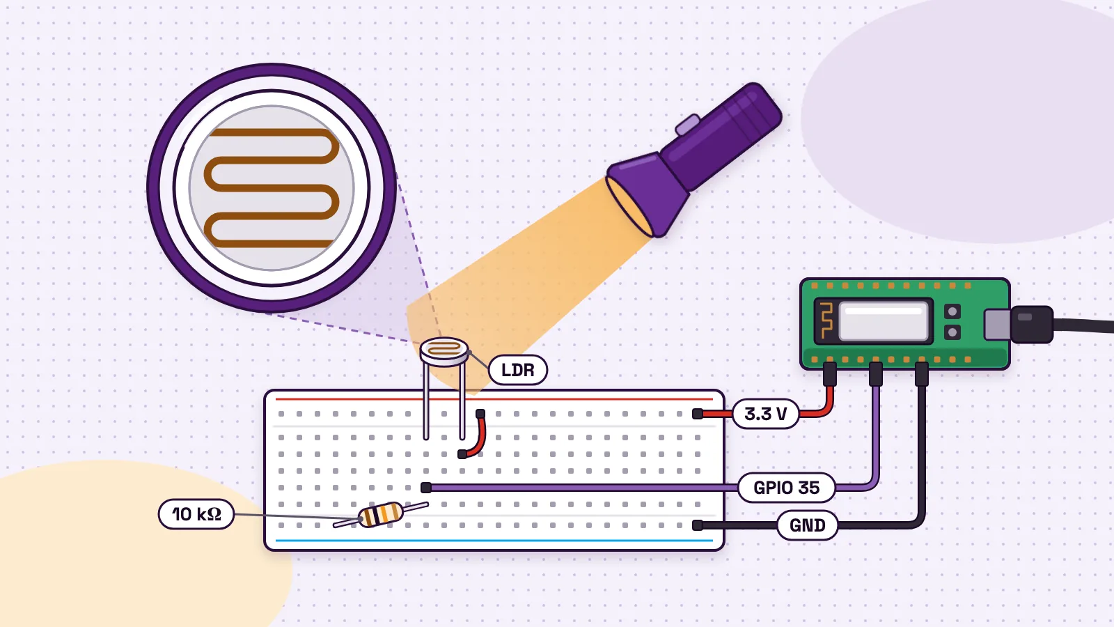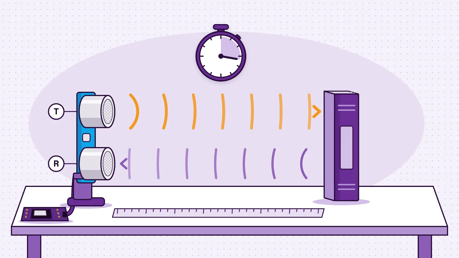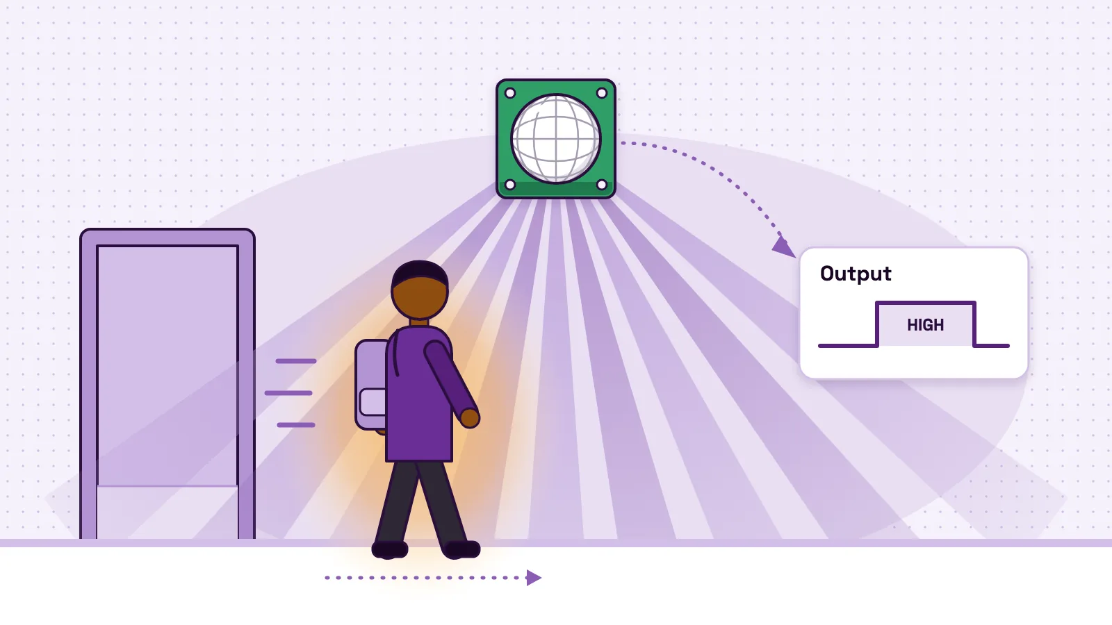
A PIR motion sensor is a small sensor that switches its output on when something warm, such as a person or a pet, moves in front of it. PIR stands for passive infrared. Warm bodies give off infrared light that your eyes cannot see. The sensor watches that light through a white plastic dome. When the pattern of warmth in front of it shifts, its output pin goes high for a set time, then drops back to low. It sends nothing out itself, which is why it is called passive.
Adafruit's PIR sensor overview (opens in a new tab) calls PIR sensors small, inexpensive, low-power and easy to use. That is why they sit in hall lights, burglar alarms and school projects. The same design explains their weak spots: a PIR can lose someone who sits still, miss someone who walks straight at it, and fire when warm air blows across it.
What is a PIR sensor?
Everything warm gives off infrared, a kind of light with longer waves than red. The hotter something is, the more it gives off, as Adafruit's overview (opens in a new tab) puts it. A PIR sensor does not measure temperature, and it does not take a picture. It reacts to a change in the infrared reaching it.
Wikipedia's article on passive infrared sensors (opens in a new tab) explains that "passive" means the device gives off no energy to detect anything. Its window can filter the light to 8–14 micrometres, the band closest to what human bodies give off. An active sensor works the other way. The kit's HC-SR04 distance sensor sends out 40 kHz sound and times the echo, according to the HC-SR04 datasheet (opens in a new tab).
The PIR in the MakerBuddy IoT Kit V1.0 is the HC-SR501. It plugs into its own labelled socket, marked 18, and the board reads it on GPIO 18. The visual guide to the types of sensors used in student projects shows where it fits among the kit's nine sensors.
How does a PIR sensor work? The core working principle
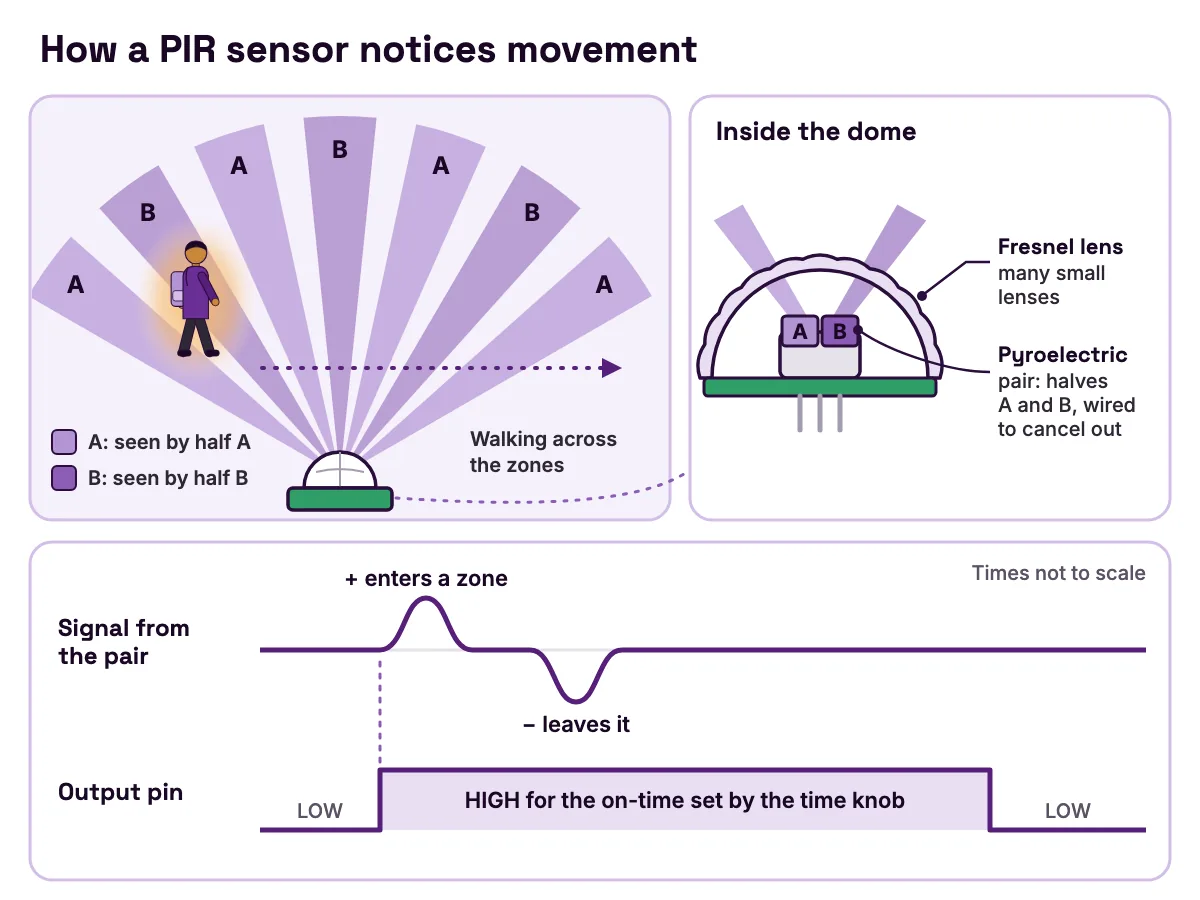
- Warm things glow in infrared. A person crossing a room is a moving patch of extra infrared against cooler walls.
- The dome is a Fresnel lens: many small lenses moulded into thin plastic, each one aiming a slice of the room at the sensor inside.
- Inside sits a pyroelectric pair: two patches of a material that makes a tiny voltage when it warms or cools. They are wired so that they cancel out when both see the same thing.
- Movement makes a difference. As you cross from one slice into the next, one patch warms before the other. They stop cancelling, and a small pulse appears.
- A chip turns the pulse into on or off, and holds the output pin high for a set time.
- Warm-up comes first. After power-on, the module needs about a minute before its output means anything.
Adafruit's explanation of how PIRs work (opens in a new tab) describes the pulses: positive as a warm body enters one half's view, negative as it leaves. The Adafruit overview (opens in a new tab) adds that most small hobby modules use a chip called the BISS0001 to turn that tiny signal into a digital output.
Why a still person disappears
Wikipedia's page on pyroelectricity (opens in a new tab) defines it as the ability of certain materials to make a temporary voltage when heated or cooled. If the temperature then stays the same, the voltage leaks away. So a PIR senses change, not presence. A person sitting perfectly still gives it nothing new to report. And because the two halves are wired against each other, a change that reaches both at once, such as the whole room slowly warming, cancels out.
Why crossing works best
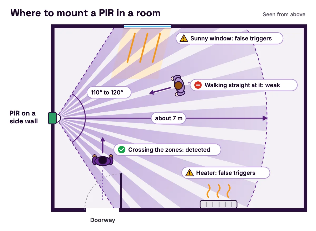
Adafruit (opens in a new tab) explains that the dome is split into many sections, each its own small Fresnel lens, with neighbouring sections aimed at different halves of the sensor. So the view is a fan of stripes with gaps between them, and each step from one stripe into the next makes a pulse. Walk straight at the sensor and you stay in the same stripes. The HC-SR501 datasheet (opens in a new tab) says the sensor is then "insensitive or does not work", and asks you to mount it so that people pass from side to side.
Why you wait a minute
The HC-SR501 datasheet (opens in a new tab) says the module needs about a minute after power-on, and may switch its output on up to three times while it settles. Adafruit's testing guide (opens in a new tab) gives 30 to 60 seconds for its own module.
PIR motion sensor range, angle and power
This is what the HC-SR501's datasheet says, including the places where it disagrees with itself.
| What | HC-SR501 datasheet | What it means for you |
|---|---|---|
| Range | Within 7 m; the distance knob sets about 3 m to 7 m | A room, not a sports hall |
| Angle | Under 120 degrees on page 1; at most 110 degrees on page 4 | A wide fan, not a narrow beam |
| Supply | 4.5 V to 20 V DC (5 V to 20 V in two places) | More than the ESP32's 3.3 V |
| Output | 3.3 V high, 0 V low | Suits a 3.3 V input pin |
| Standby current | Under 50 µA (page 1 says 65 mA) | Measure yours if it matters |
| On-time | Adjustable, about 5 s to 300 s | Set with the time knob |
| Block time | 2.5 s by default (page 1 says 0.2 s) | A pause after each trigger |
| Working temperature | −15 to +70 °C | Fine indoors |
- What
- Range
- HC-SR501 datasheet
- Within 7 m; the distance knob sets about 3 m to 7 m
- What it means for you
- A room, not a sports hall
- What
- Angle
- HC-SR501 datasheet
- Under 120 degrees on page 1; at most 110 degrees on page 4
- What it means for you
- A wide fan, not a narrow beam
- What
- Supply
- HC-SR501 datasheet
- 4.5 V to 20 V DC (5 V to 20 V in two places)
- What it means for you
- More than the ESP32's 3.3 V
- What
- Output
- HC-SR501 datasheet
- 3.3 V high, 0 V low
- What it means for you
- Suits a 3.3 V input pin
- What
- Standby current
- HC-SR501 datasheet
- Under 50 µA (page 1 says 65 mA)
- What it means for you
- Measure yours if it matters
- What
- On-time
- HC-SR501 datasheet
- Adjustable, about 5 s to 300 s
- What it means for you
- Set with the time knob
- What
- Block time
- HC-SR501 datasheet
- 2.5 s by default (page 1 says 0.2 s)
- What it means for you
- A pause after each trigger
- What
- Working temperature
- HC-SR501 datasheet
- −15 to +70 °C
- What it means for you
- Fine indoors
Every figure in the table comes from the HC-SR501 datasheet (Electrokit copy) (opens in a new tab). The ESP32 datasheet (opens in a new tab) gives the chip's characteristics at 3.3 V, which is why a 3.3 V output suits it. Treat a cheap module's numbers as a guide and measure your own. Other modules differ: Adafruit's PIR overview (opens in a new tab) gives up to 6 m (20 feet) and a 110 by 70 degree view for the one it sells.
Why the range is not one number
- Direction: people crossing the view are noticed far more easily than people walking straight at it, which the HC-SR501 datasheet (opens in a new tab) says can leave the sensor insensitive.
- Heat: the HC-SR501 datasheet (opens in a new tab) says the range gets slightly shorter when the room reaches 30–32 °C. A warm room looks more like a warm body, so expect less range in a hot summer classroom.
- Speed: the electronics ignore slowly changing signals, as the passive infrared sensor article (opens in a new tab) notes, so a slow creep can stay hidden. The Red Light, Green Light challenge in Week 13 tests exactly this.
PIR sensor settings: sensitivity, time delay and trigger mode
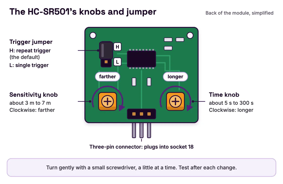
The HC-SR501 has two small knobs and a trigger jumper. Turn the knobs gently with a small screwdriver, a little at a time, and test after each change. In class, ask your teacher first.
| Setting | What it changes | Datasheet range |
|---|---|---|
| Sensitivity knob | How far away it notices movement | Clockwise for farther, about 7 m; anticlockwise for nearer, about 3 m |
| Time knob | How long the output stays high after a trigger | Clockwise for longer, about 300 s; anticlockwise for shorter, about 5 s |
| Jumper on H (default) | Repeat trigger: each movement restarts the timer, so the output stays high while people keep moving | None |
| Jumper on L | Single trigger: the output drops when the time is up, even if people are still moving | None |
| Block time | After the output drops, the sensor ignores all movement | 2.5 s by default |
- Setting
- Sensitivity knob
- What it changes
- How far away it notices movement
- Datasheet range
- Clockwise for farther, about 7 m; anticlockwise for nearer, about 3 m
- Setting
- Time knob
- What it changes
- How long the output stays high after a trigger
- Datasheet range
- Clockwise for longer, about 300 s; anticlockwise for shorter, about 5 s
- Setting
- Jumper on H (default)
- What it changes
- Repeat trigger: each movement restarts the timer, so the output stays high while people keep moving
- Datasheet range
- None
- Setting
- Jumper on L
- What it changes
- Single trigger: the output drops when the time is up, even if people are still moving
- Datasheet range
- None
- Setting
- Block time
- What it changes
- After the output drops, the sensor ignores all movement
- Datasheet range
- 2.5 s by default
The ranges and jumper modes come from the HC-SR501 datasheet (opens in a new tab), which also gives the on-time as 0.3 seconds to 5 minutes in two other places. The block time has no knob. Adafruit's testing guide (opens in a new tab) says changing it on its module takes a soldering iron.
Worked example: how far to turn the time knob
Adafruit's testing guide (opens in a new tab) gives the formula for the time knob on its module:
Tx = 24,576 × (10 kΩ + R) × 0.01 µF
R is how much of the knob's 1 MΩ you have turned in. Ohms times farads gives seconds, so you can work it by hand. Since 24,576 × 0.000 000 01 F = 0.000 245 76, every ohm adds 0.000 245 76 seconds.
| Knob position | R | Sum | On-time |
|---|---|---|---|
| All the way anticlockwise | 0 | 0.000 245 76 × 10,000 | 2.5 s |
| A quarter turned | 250 kΩ | 0.000 245 76 × 260,000 | 63.9 s |
| Halfway | 500 kΩ | 0.000 245 76 × 510,000 | 125.3 s |
| All the way clockwise | 1 MΩ | 0.000 245 76 × 1,010,000 | 248.2 s |
- Knob position
- All the way anticlockwise
- R
- 0
- Sum
- 0.000 245 76 × 10,000
- On-time
- 2.5 s
- Knob position
- A quarter turned
- R
- 250 kΩ
- Sum
- 0.000 245 76 × 260,000
- On-time
- 63.9 s
- Knob position
- Halfway
- R
- 500 kΩ
- Sum
- 0.000 245 76 × 510,000
- On-time
- 125.3 s
- Knob position
- All the way clockwise
- R
- 1 MΩ
- Sum
- 0.000 245 76 × 1,010,000
- On-time
- 248.2 s
Now run it backwards for a one-minute on-time:
10 kΩ + R = 60 ÷ 0.000 245 76 = 244,141 Ω, so R = 234 kΩ
That is about 23% of the knob, if it turns evenly. It matches Adafruit's advice (opens in a new tab) of about a quarter turn for a minute. But your HC-SR501 may use different parts: its datasheet (opens in a new tab) gives 5 to 300 seconds, not 2.5 to 248. So never trust the knob's position. Time it, with a stopwatch or the sketch further down.
For most builds, we suggest you set the time knob short, leave the jumper on H and let a rule decide how long things stay on. The Motion Alarm, the Intruder Alert and the Digital Pet in the MakerBuddy project idea library are all no-code rule builds with the PIR, so you can try this on any of them. The motion sensor alarm build guide takes the alarm further.
The kit's PIR on GPIO 18, live on the MakerBuddy dashboard
Unplug the USB cable first. Then plug the HC-SR501 into the three-pin socket marked 18 on the bottom edge of the board. It fits only one way, so never force it. Plug the cable back in and give the sensor its minute. Week 13, Security Sensing walks through this, and its Try It: Sneak Past the Sensor demo lets you practise in the browser first. The board comes in purple or green; both colours are the same board.
- Dashboard: the Motion Sensor card shows Motion or None. The browser extension words them Detected and No Motion.
- Text screen: the
{motion}wildcard shows YES or NO, as the text screen notes in the technical details list. - Rules: Motion Sensor can only be tested as Equal to (==) True or False.
- Your own programs: the reading is called
mdin the MakerBuddy REST API documentation.
The board reads GPIO 18 once a second and adds no hold time of its own, so the card shows the module's own output, shaped by its knobs. The dashboard gets fresh readings at most every 2 seconds.
| What happens | Time after the PIR output goes high |
|---|---|
| The board reads GPIO 18 | 0 to 1 s |
| A Condition rule's 0.3-second check is passed | 0.3 to 1.3 s |
| The Motion Sensor card changes | Up to about 3 s |
- What happens
- The board reads GPIO 18
- Time after the PIR output goes high
- 0 to 1 s
- What happens
- A Condition rule's 0.3-second check is passed
- Time after the PIR output goes high
- 0.3 to 1.3 s
- What happens
- The Motion Sensor card changes
- Time after the PIR output goes high
- Up to about 3 s
These are MakerBuddy's own timings, from the firmware and the automation rules documentation. The adjustment notes in the HC-SR501 datasheet (opens in a new tab) put the shortest on-time at about 5 seconds. If that holds for your module, a trigger cannot slip between two once-a-second checks. It can only arrive up to a second late. But the same datasheet also gives 0.3 seconds in two places, and an output that short could fall between two checks. Time yours with the sketch further down, and turn the time knob up a little if it stays high for under a second.
Watch the card on a laptop, an iPhone or an iPad; Android phones cannot control the board yet. There are no accounts, and the readings stay on your own Wi-Fi network.
Worked example: a no-code hall light that stays on for a minute
The goal: when someone walks in, the blue light turns on and stays on for at least a minute. It is the bonus challenge at the end of Week 13, built with a Condition rule from Week 26, Sensor-Based Control.
- 1
With the USB cable unplugged, plug the PIR into socket 18. Power up and wait a minute.
- 2
Turn the time knob all the way anticlockwise and leave the jumper on H.
- 3
Open the Rule Engine tab, name a rule
HallLightand choose the Condition loop mode. - 4
Set Sensor to Motion Sensor, Equal to (==), True.
- 5
Add step 1: LED On, Value 255, Delay (ms) 60000. That is 60,000 milliseconds, one minute.
- 6
Add step 2: LED Off, Delay (ms) 0. Save. Rules run on the board, so the light keeps working after you close the dashboard.
Predict what happens first, then test it. These timings assume the datasheet's shortest on-time of about 5 seconds:
| Time | What happens |
|---|---|
| 0 s | You walk in and keep moving for 3 seconds. The PIR output goes high |
| 0.3 to 1.3 s | The board has read the pin and the 0.3-second check is passed. The rule starts: LED on |
| About 8 s | The output drops, about 5 seconds after your last movement |
| Up to 1.3 s later | The rule sees False and treats the run it is in as its last |
| About 61 s | The one-minute delay ends. Step 2: LED off. The rule waits for the next movement |
- Time
- 0 s
- What happens
- You walk in and keep moving for 3 seconds. The PIR output goes high
- Time
- 0.3 to 1.3 s
- What happens
- The board has read the pin and the 0.3-second check is passed. The rule starts: LED on
- Time
- About 8 s
- What happens
- The output drops, about 5 seconds after your last movement
- Time
- Up to 1.3 s later
- What happens
- The rule sees False and treats the run it is in as its last
- Time
- About 61 s
- What happens
- The one-minute delay ends. Step 2: LED off. The rule waits for the next movement
Why does one rule do the whole job? A Condition rule that turns false mid-run finishes that run, so its clean-up step still happens, as the rules section of the technical details explains. If people are still moving when the minute ends, the condition is still true. The rule starts again, and the light comes straight back on.
Notice that the minute counts from the start of the run, not from your last movement. Someone who walks about until second 50 gets only about 11 seconds of light after they stop. If that matters, set the time knob to about a minute and use two Condition rules instead: Motion Sensor equal to True turns the light on, and equal to False turns it off. The two-rule security light in the visual programming guide builds that pattern. The catch: anyone can read a rule's delay on the dashboard, but nobody can see where a knob is set.
To make the light come on only in the dark, tick Add a second sensor, choose AND and add Light Level less than a number you measured. The guide to if-then statements explained with real sensors shows what AND does to a rule.
Time your own PIR with a short Arduino sketch
This sketch checks the PIR 100 times a second. It waits out the warm-up, then prints how long the output stays high and low. Use the "esp32 by Espressif Systems" boards package (version 3.x), the ESP32 Dev Module board and the Serial Monitor at 115200 baud.
// MakerBuddy board (ESP32 Dev Module): time the PIR motion sensor's output.
// Uploading this replaces the MakerBuddy firmware until you upload that again.

const int PIR_PIN = 18;                  // HC-SR501 in the socket marked 18
const int LED_PIN = 12;                  // built-in blue light
const unsigned long WARM_UP_MS = 60000;  // the datasheet's one-minute settling time

int lastState = LOW;
unsigned long changedAt = 0;  // when the output last changed (ms)
bool ready = false;
int triggers = 0;

void setup() {
  Serial.begin(115200);       // match the Serial Monitor speed
  pinMode(PIR_PIN, INPUT);    // the PIR drives the pin high or low itself
  pinMode(LED_PIN, OUTPUT);
  Serial.println("Warming up for 60 s. Keep still.");
}

void loop() {
  unsigned long now = millis();
  int state = digitalRead(PIR_PIN);
  digitalWrite(LED_PIN, state);  // the blue light copies the PIR output

  if (!ready && now >= WARM_UP_MS) {
    ready = true;
    changedAt = now;  // start timing from here, not from power-on
    Serial.println("Ready. Walk across the sensor's view.");
  }

  if (state != lastState) {
    float seconds = (now - changedAt) / 1000.0;
    if (!ready) {
      Serial.println("Change during warm-up (ignored)");
    } else if (state == HIGH) {
      triggers++;
      Serial.printf("Trigger %d: HIGH after %.1f s low\n", triggers, seconds);
    } else {
      Serial.printf("LOW after %.1f s high\n", seconds);
    }
    changedAt = now;
    lastState = state;
  }

  delay(10);  // check 100 times a second
}- 1
pinMode(PIR_PIN, INPUT)needs no pull-up resistor, because the HC-SR501 drives its own output to 3.3 V or 0 V. - 2
The warm-up block ignores the first minute, when the output may switch on by itself.
- 3
The
if (state != lastState)block runs only when the output changes, and notes the time withmillis().
Now try three experiments. Wave once and keep still: "LOW after" is your real on-time, to compare with the 5 to 300 seconds in the HC-SR501 datasheet (opens in a new tab). Keep waving for 20 seconds with the jumper on H: the output stays high the whole time. Wave again the moment it goes low: the next "HIGH after" shows the block time, 2.5 seconds by default.
When you finish, put the MakerBuddy firmware back with the steps in install by USB. For other boards and more code, see motion sensor with Arduino or ESP32: wiring and code.
PIR vs other motion sensors: which one notices a person?
"Motion sensor" is the family name, and PIR is one member. Wikipedia's article on motion detectors (opens in a new tab) also lists microwave, ultrasonic, tomographic and camera-based types. It notes that many dual-technology sensors combine a PIR and a microwave sensor in one unit.
| PIR (HC-SR501) | Ultrasonic (HC-SR04) | Infrared obstacle sensor (TCRT5000) | Light sensor as a shadow sensor | |
|---|---|---|---|---|
| What it senses | A change in infrared from warm, moving bodies | How long a sound echo takes to return | Infrared from its own emitter, reflected back | A drop in light falling on it |
| Passive or active | Passive | Active, sends 40 kHz sound | Active, sends 950 nm infrared | Passive |
| Reach | Up to 7 m | 2 cm to 400 cm | 0.2 mm to 15 mm | Only shadows that fall on it |
| A person standing still | Fades out | Still measured | Seen while within reach | Seen while the shadow stays |
| In the MakerBuddy kit | Yes, socket 18 | Yes | No | Yes, built into the board |
- What it senses
- PIR (HC-SR501)
- A change in infrared from warm, moving bodies
- Ultrasonic (HC-SR04)
- How long a sound echo takes to return
- Infrared obstacle sensor (TCRT5000)
- Infrared from its own emitter, reflected back
- Light sensor as a shadow sensor
- A drop in light falling on it
- Passive or active
- PIR (HC-SR501)
- Passive
- Ultrasonic (HC-SR04)
- Active, sends 40 kHz sound
- Infrared obstacle sensor (TCRT5000)
- Active, sends 950 nm infrared
- Light sensor as a shadow sensor
- Passive
- Reach
- PIR (HC-SR501)
- Up to 7 m
- Ultrasonic (HC-SR04)
- 2 cm to 400 cm
- Infrared obstacle sensor (TCRT5000)
- 0.2 mm to 15 mm
- Light sensor as a shadow sensor
- Only shadows that fall on it
- A person standing still
- PIR (HC-SR501)
- Fades out
- Ultrasonic (HC-SR04)
- Still measured
- Infrared obstacle sensor (TCRT5000)
- Seen while within reach
- Light sensor as a shadow sensor
- Seen while the shadow stays
- In the MakerBuddy kit
- PIR (HC-SR501)
- Yes, socket 18
- Ultrasonic (HC-SR04)
- Yes
- Infrared obstacle sensor (TCRT5000)
- No
- Light sensor as a shadow sensor
- Yes, built into the board
The reach figures come from the HC-SR501 (opens in a new tab), HC-SR04 (opens in a new tab) and TCRT5000 (opens in a new tab) datasheets. A US Department of Energy fact sheet on selecting lighting controls (opens in a new tab) makes the same split for buildings. Infrared occupancy sensors work well where the whole room is in the sensor's view, while ultrasonic ones can detect motion even around corners.
Pick the PIR to know whether a warm body is moving anywhere across a wide area. Pick the distance sensor to know how far away something is, warm or not. The Shadow Alarm in the project library combines the light sensor with the PIR. The guide to how an ultrasonic sensor measures distance covers the HC-SR04, and the comparison of IR and PIR sensors explains why an IR sensor is a different part.
Common PIR problems and how to fix them
The guide to PIR sensitivity, time delay and false triggers goes further on tuning.
It switches on by itself just after power-on
- Symptom: Motion once or twice in the first minute, with nobody there.
- Cause: warm-up. The HC-SR501 datasheet (opens in a new tab) allows up to three outputs in the first minute.
- Fix: wait a full minute after power-on before you test or trust a rule.
Motion stays on long after everyone stops
- Symptom: the card stays on Motion for minutes.
- Cause: the time knob is turned up, as far as about 300 seconds on the datasheet (opens in a new tab), and on H every movement restarts it.
- Fix: turn the time knob anticlockwise, then time the result with the sketch.
It misses people who walk straight towards it
- Symptom: someone walks right up to the sensor and nothing happens.
- Cause: both halves of the sensor change almost equally, so there is no difference to report.
- Fix: mount it so people cross its view, for example on a side wall looking across a doorway.
It loses someone who is sitting still
- Symptom: a person reading quietly makes the card go back to None.
- Cause: pyroelectric material (opens in a new tab) only makes a voltage while its temperature is changing.
- Fix: this is how every PIR works. To know that someone is still there, add the distance sensor.
It triggers when nobody is there
- Symptom: Motion in an empty room.
- Cause: the HC-SR501 datasheet (opens in a new tab) warns against lights shining close to the lens and moving air. The passive infrared sensor article (opens in a new tab) adds strong sunlight and warm or cold air from vents, and Adafruit's overview adds pets.
- Fix: move it away from windows, heaters, fans and vents, and turn the sensitivity down a little.
The card never changes from None
- Symptom: you wave, and the card does not move.
- Cause: the plug is not fully home, it is in the wrong socket or the sensor is still warming up.
- Fix: with the USB cable unplugged, check that the plug sits firmly in socket 18. After the warm-up, wave about a metre away, across its view, and allow 3 seconds.
What PIR sensors are used for, and where they fall short
The passive infrared sensor article (opens in a new tab) names the main uses: burglar alarms and lights that switch themselves on. In a US government office building described in the Department of Energy fact sheet (opens in a new tab), occupancy sensors alone cut lighting energy in private offices by 25% on weekdays. The same fact sheet warns that too short a delay annoys the people in the room, and that a sensor which can see passers-by in a hallway switches lights on for nobody.
Know its limits too.
- It cannot count people or tell how close they are, as the Adafruit PIR overview (opens in a new tab) points out.
- It records no images. It can tell that someone moved, never who, which is good for privacy.
- A kit alarm is a learning build, not home security. The board has no clock, so it cannot log when an alarm went off. Its local web connection has no password, so use it only on a Wi-Fi network you trust and never open it to the internet.
The HC-SR501 is one of the plug-in parts in the MakerBuddy IoT Kit, with its own labelled socket. More sensor guides are on the MakerBuddy blog.
FAQ
What does PIR stand for?
PIR stands for passive infrared. Infrared is light we cannot see, given off by anything warm. Passive means the sensor only receives it and sends nothing out.
What is the difference between a motion sensor and a PIR sensor?
A motion sensor is any device that detects movement, and a PIR sensor is one kind of motion sensor. Others use microwaves, ultrasound or a camera, as the motion detector article (opens in a new tab) lists. A PIR is the passive, low-power choice that reacts to warm bodies moving.
What is the difference between IR sensor and PIR sensor?
An IR obstacle sensor shines its own infrared light and watches for the reflection, so it is active and short-range. The TCRT5000 datasheet (opens in a new tab) gives 0.2 mm to 15 mm. A PIR has no light of its own. It senses the infrared that warm bodies give off, across a whole room.
How far can a PIR sensor detect?
The HC-SR501 reaches up to 7 m, and its sensitivity knob sets about 3 m to 7 m, according to its datasheet (opens in a new tab). Real range is shorter when people walk straight at it, move very slowly or the room is hot.
Will a PIR detect a car?
In principle it can, if the car moves across its zones and looks warmer or cooler in infrared than what is behind it. The passive infrared sensor article (opens in a new tab) explains that detection depends on that difference. A car that has been parked for hours gives it nothing new. For parking projects, the ultrasonic sensor measures how far away the car is, warm or cold.
Do PIR sensors use a lot of electricity?
No. The HC-SR501 datasheet (opens in a new tab) gives a standby current under 50 microamps. At 5 V that is 5 × 0.000 05 = 0.000 25 W, a quarter of a milliwatt. Its first page says 65 mA, which would be 0.325 W, so measure your own module with a multimeter if the number matters.
What are PIR sensors used for?
Burglar alarms and automatic lighting are the classic uses, according to the passive infrared sensor article (opens in a new tab). In school projects they run motion alarms, visitor counters and hall lights. Week 13 of the MakerBuddy course teaches the sensor with a live dashboard card.
Can a PIR sensor detect a person who is not moving?
Usually not for long. A still person causes almost no change in infrared, so the output drops when its on-time runs out. If you need to know that someone is still there, pair the PIR with a distance sensor.
Sources
- HC-SR501 PIR motion sensor datasheet (Electrokit copy) (opens in a new tab): within 7 m, 3–7 m distance knob, angle given as under 120 and at most 110 degrees, 4.5–20 V (and 5–20 V) supply, 3.3 V output, quiescent current under 50 µA (and 65 mA on page 1), 5–300 s delay (and 0.3 s to 5 min), 2.5 s block time (and 0.2 s on page 1), H and L trigger modes with repeat trigger as default, one-minute warm-up with 0–3 outputs, dual A/B probe, best detection across the view, shorter range at 30–32 °C, lights and air flow as interference, optional photosensitive control, −15 to +70 °C.
- Adafruit, PIR Motion Sensor overview (opens in a new tab): small, inexpensive, low-power; pyroelectric sensor split in two halves; BISS0001 chip; up to 20 feet (6 m), 110 × 70 degrees, 5–12 V supply; cannot count people or tell distance; pets.
- Adafruit, How PIRs work (opens in a new tab): positive and negative differential changes; faceted Fresnel lens and interleaved detection areas.
- Adafruit, Testing a PIR (opens in a new tab): retriggering and non-retriggering jumper modes, Tx = 24576 × (10K + Rtime) × 0.01 µF, about a quarter turn for one minute, 30–60 s to stabilise, minimum off time changed only by soldering.
- Wikipedia, Passive infrared sensor (opens in a new tab): meaning of passive, 8–14 µm window, slow changes ignored, zones set by the lens, uses in burglar alarms and automatic lighting, sunlight and vents, infrared contrast with the background.
- Wikipedia, Pyroelectricity (opens in a new tab): a temporary voltage when heated or cooled that leaks away when the temperature stays constant.
- Wikipedia, Motion detector (opens in a new tab): passive infrared, microwave, ultrasonic, tomographic and camera-based detectors; PIR and microwave dual-technology sensors.
- US Department of Energy, FEMP: How to select lighting controls for offices and public buildings (opens in a new tab): infrared and ultrasonic occupancy sensors, delay and placement advice, 25% weekday lighting savings in private offices in the Phillip Burton Federal Building case study.
- Vishay, TCRT5000 reflective optical sensor datasheet (opens in a new tab): infrared emitter and phototransistor, 950 nm, 0.2–15 mm operating range.
- Elecfreaks, HC-SR04 ultrasonic ranging module datasheet (SparkFun copy) (opens in a new tab): 10 µs trigger, 40 kHz, 2–400 cm range.
- Espressif, ESP32 datasheet (opens in a new tab): electrical characteristics at 3.3 V.