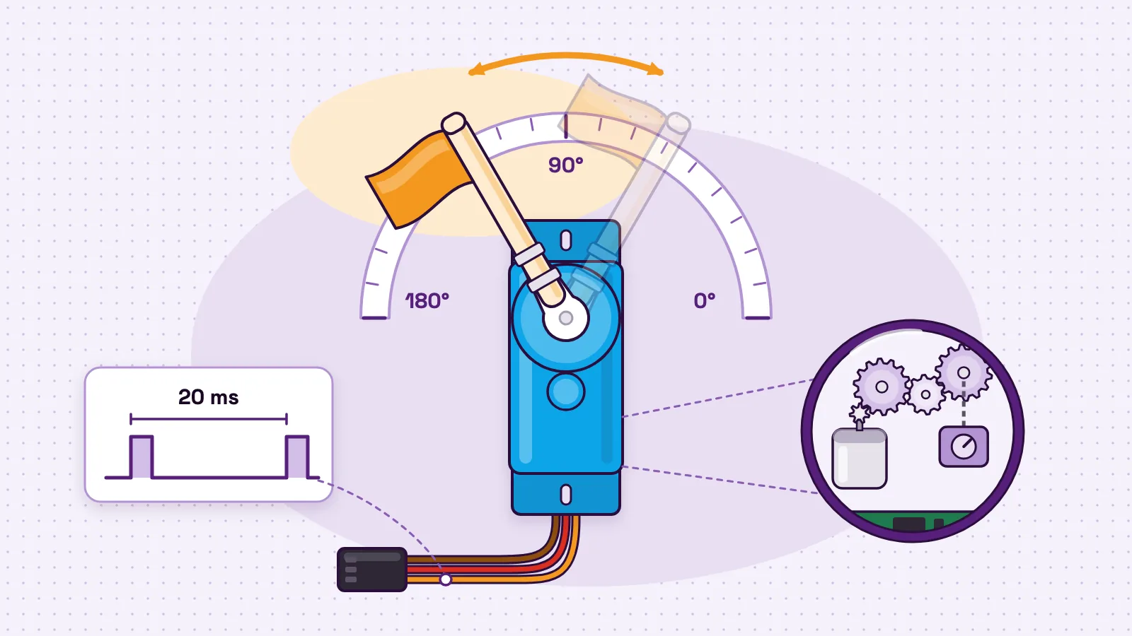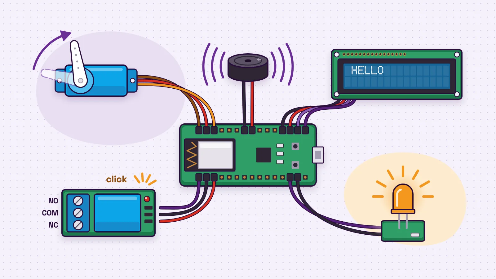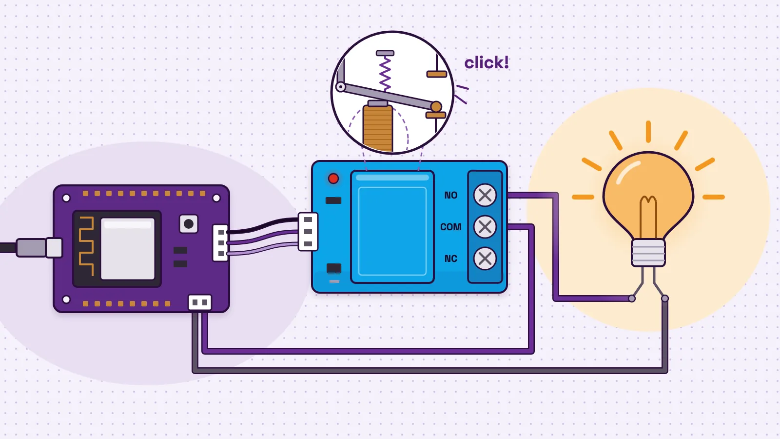
What is a relay? A relay is a switch that electricity flips for you. A small current flows through a coil of wire, the coil becomes a magnet, and the magnet pulls a metal arm that opens or closes a second, separate circuit. That is how a small signal switches a big load. A microcontroller pin makes the decision, and the relay's contacts carry the power to a fan, a lamp or a pump. The two circuits never touch each other electrically.
The name fits. In a relay race, one runner hands the baton to the next. In an electrical relay, a weak signal hands the job on to a stronger circuit.
Every hands-on example here uses the relay in the MakerBuddy kit, which Lesson 15 on relay control and electrical isolation teaches. In this kit, the relay only ever switches small low-voltage things.
What is a relay? A plain definition
Panasonic's introduction to relays (opens in a new tab) describes a relay as two parts: an electromagnet and a contact mechanism. Arduino's guide to its relay shield (opens in a new tab) says relays let a low-power microcontroller handle circuits that use much more power than the board could handle directly.
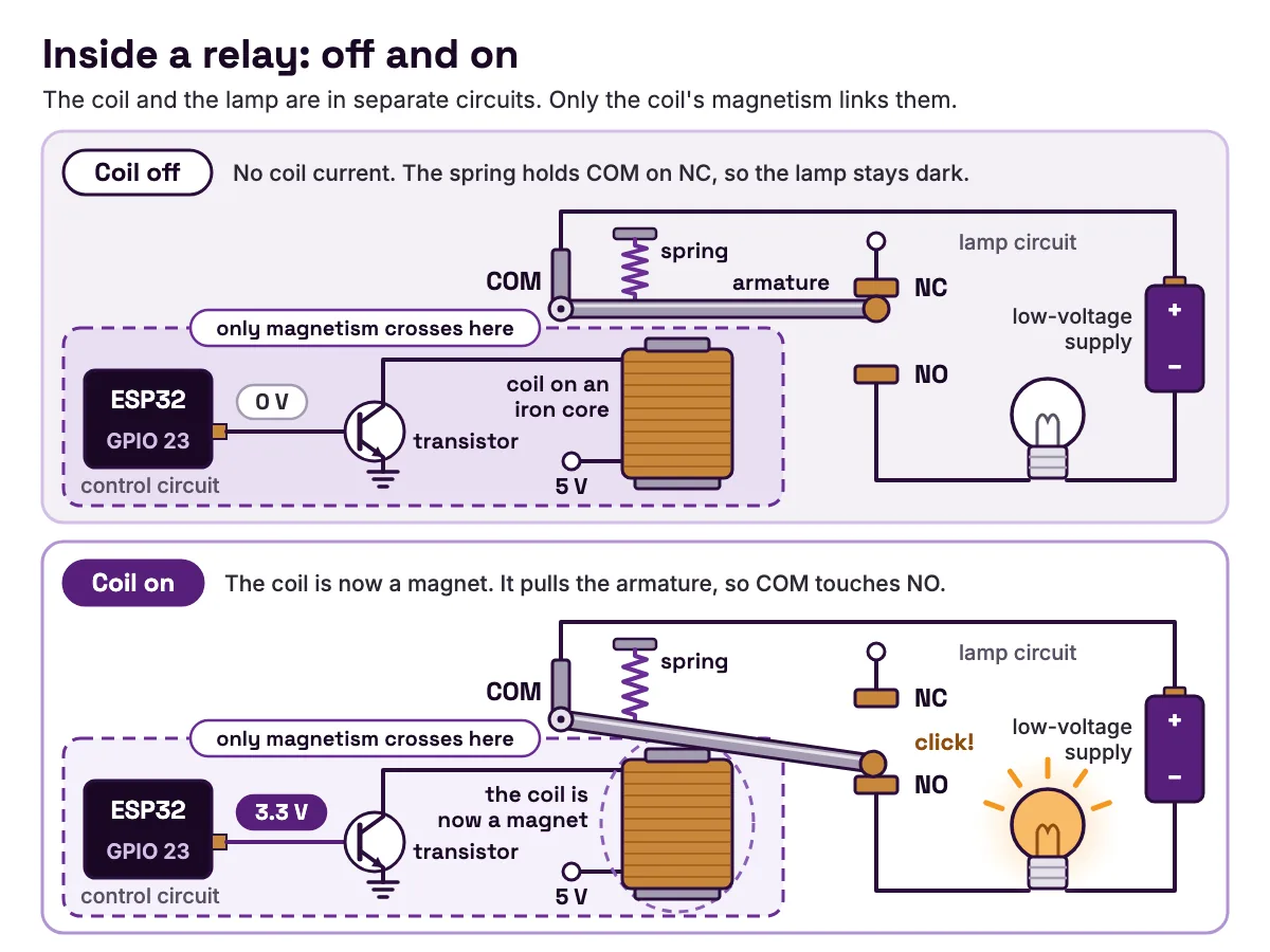
So every relay has two sides.
- The control side is the coil. It needs only a small current.
- The load side is the contacts. They carry the current for the thing you want to switch, which engineers call the load.
"Relay switch" is a fair name. You press a wall switch with your finger. A relay is pressed by a magnet, and the magnet is switched on by a signal from a thermostat, a button or a microcontroller pin.
Only magnetism links the two sides. Lesson 15 calls this galvanic isolation: no wire joins them, so a fault on the load side cannot travel back along a wire into the computer that gave the order. Our guide to open, closed and short circuits explains what opening and closing a circuit means. A relay does exactly that, from a distance.
Inside a relay: coil, armature, spring and contacts
Take the cover off a small relay and you find four kinds of parts.
| Part | What it is | What it does |
|---|---|---|
| Coil | Many turns of thin copper wire around an iron core | Becomes a magnet while current flows |
| Armature | A small metal arm on a hinge | Gets pulled towards the coil when it is magnetic |
| Spring | A thin strip of springy metal | Pulls the armature back when the coil switches off |
| Contacts | Metal pads named COM, NO and NC | Open or close the load circuit |
- Part
- Coil
- What it is
- Many turns of thin copper wire around an iron core
- What it does
- Becomes a magnet while current flows
- Part
- Armature
- What it is
- A small metal arm on a hinge
- What it does
- Gets pulled towards the coil when it is magnetic
- Part
- Spring
- What it is
- A thin strip of springy metal
- What it does
- Pulls the armature back when the coil switches off
- Part
- Contacts
- What it is
- Metal pads named COM, NO and NC
- What it does
- Open or close the load circuit
The three contacts are where beginners get stuck.
- COM (common) moves with the armature. It is always part of the load circuit.
- NC (normally closed) touches COM while the coil has no power.
- NO (normally open) touches COM only while the coil has power.
"Normally" means "when the coil is off". So a load wired between COM and NO stays off until the relay switches on. A load wired between COM and NC does the opposite.
| Coil | COM touches | Load on COM and NO | Load on COM and NC |
|---|---|---|---|
| Off | NC | Off | On |
| On | NO | On | Off |
- Coil
- Off
- COM touches
- NC
- Load on COM and NO
- Off
- Load on COM and NC
- On
- Coil
- On
- COM touches
- NO
- Load on COM and NO
- On
- Load on COM and NC
- Off
The blue relay on the MakerBuddy kit's module is marked SRD-05VDC-SL-C. The LCSC listing for this Songle relay (opens in a new tab) calls its contacts 1C or SPDT (single pole, double throw): one COM that flips between NC and NO. In Songle's datasheet (opens in a new tab), 05VDC is the coil voltage and the final C means changeover contacts. Our coming guide to normally open vs normally closed relay contacts shows when to choose NC on purpose.
How does a relay work? Step by step on a real board
Here is what happens on the MakerBuddy kit when you switch the relay on, as Lesson 15 explains it.
- 1
The ESP32, the small computer on the board, sets GPIO 23 to 3.3 V.
- 2
A small transistor on the relay module switches on.
- 3
Current from the board's 5 V supply flows through the coil.
- 4
The coil becomes a magnet and pulls the armature. You hear a click, and the module's indicator LED lights.
- 5
COM leaves NC and touches NO. The load circuit is complete, so the fan or bulb gets power.
- 6
When the pin goes back to 0 V, the coil stops being a magnet, and the spring pulls the armature back with a second click.
The click is your best clue when something does not work. A click means the control side is fine, so look for the problem on the load side.
The LCSC listing (opens in a new tab) gives an operate time and a release time of 10 ms each, about a hundredth of a second. That is why the stopwatch challenge in Lesson 15 mostly times the student's own thumb.
The coil does not need exactly 5 V. Songle's datasheet (opens in a new tab) says the relay pulls in at no more than 75% of its rated coil voltage and is sure to let go once the voltage falls below 10% of it. For a 5 V coil, 3.75 V is enough to be sure it switches on, and below 0.5 V you can be sure it has switched off.
Why a pin needs a relay module: a worked calculation
Could an ESP32 pin power the relay coil by itself? Work it out with numbers from two datasheets. Our guide to Ohm's law with real examples explains the formula used here.
Step 1: the current the coil needs. The LCSC listing (opens in a new tab) gives a 5 V coil with a resistance of 70 Ω. Current equals voltage divided by resistance.
I = V / R
I = 5 V / 70 Ω
I = 0.0714 A = 71.4 mA

Power = V × I = 5 V × 0.0714 A ≈ 0.36 W
That matches the 71.4 mA and 0.36 W in Songle's coil table (opens in a new tab).
Step 2: what one pin can give. An ESP32 pin gives 3.3 V when high. Table 5-3 of the ESP32 datasheet (opens in a new tab) lists a typical 40 mA per pin, but only at maximum drive strength. The same datasheet's pin table gives GPIO 23 a default drive strength of about 20 mA.
Step 3: compare them.
| What we check | The coil needs | One ESP32 pin gives | Result |
|---|---|---|---|
| Voltage | 3.75 V or more to be sure it pulls in | 3.3 V at most | Too low |
| Current | 71.4 mA at 5 V | About 20 mA by default, 40 mA at full drive | Too little |
- What we check
- Voltage
- The coil needs
- 3.75 V or more to be sure it pulls in
- One ESP32 pin gives
- 3.3 V at most
- Result
- Too low
- What we check
- Current
- The coil needs
- 71.4 mA at 5 V
- One ESP32 pin gives
- About 20 mA by default, 40 mA at full drive
- Result
- Too little
Table note: coil figures from the Songle datasheet (opens in a new tab), pin figures from the ESP32 datasheet (opens in a new tab).
Even at 3.3 V, the coil would try to draw 3.3 ÷ 70 = 47 mA. The pin's voltage would sag, and the relay might click or might not.
Step 4: what the module does. On a relay module, the pin only switches a small transistor. Arduino's transistor guide (opens in a new tab) explains that a small current into a transistor's base closes a circuit between its other two pins. Here that circuit connects the coil to the board's 5 V supply. The pin gives the order. The supply does the work.
Step 5: the big load. Songle's datasheet (opens in a new tab) offers this relay family with contact loads of 7 A, 10 A or 15 A. Even 7 A is about 100 times the 71.4 mA the coil uses. That gap is the whole idea of a relay. Lesson 15 adds that the mains ratings printed on relays are for trained electricians working inside proper enclosures.
What else is on a relay module
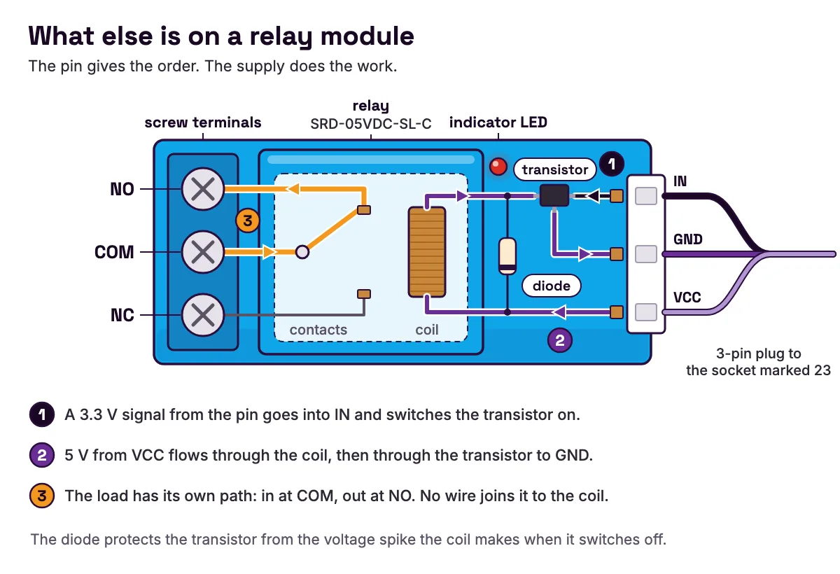
- A transistor switches the coil, as in Step 4.
- A diode across the coil protects that transistor from the voltage spike a coil makes when it switches off. TE Connectivity's note on relay coil suppression (opens in a new tab) says a 12 V DC relay may generate 1,000 to 1,500 volts during turn-off, and that a diode removes that spike.
- An indicator LED lights while the coil is on.
- Screw terminals for COM, NO and NC.
- IN, GND and VCC pins for the signal, ground and coil power. On the kit, these end in a 3-pin plug that fits the socket marked 23 only one way.
The kit module's screw labels are printed in Chinese. To find them, set a multimeter to continuity (beep) with nothing wired to the screws. The pair that beeps with the relay off is COM and NC. With the relay on, it is COM and NO. The screw in both pairs is COM.
Types of relays compared
Panasonic's introduction to relays (opens in a new tab) splits control relays into two families. Mechanical relays open and close their contacts by moving them. Semiconductor relays, which include solid-state relays, have no moving contact. The kit's relay is the mechanical kind, also called electromechanical. The table adds a transistor, which can also act as an electronic switch.
| Type | How it switches | Moving parts | Holds its state with no power? | Good at | Watch out for |
|---|---|---|---|---|---|
| Electromechanical, like the kit's | A coil pulls metal contacts together | Yes | No, a spring returns it | Full isolation; you can hear it work | Contacts wear; it clicks; about 10 ms to switch |
| Latching (bistable) | One pulse sets it; another pulse resets it | Yes | Yes | Saving power | Needs separate set and reset signals |
| Solid-state (SSR) | Semiconductors, often isolated by light or a small transformer | No | No | Silent; no contacts to wear out | AC and DC versions differ; gets warm |
| Transistor (not a relay) | A semiconductor in the load circuit | No | No | Fast; speed control with PWM | No isolation; shares a ground with the controller |
- Type
- Electromechanical, like the kit's
- How it switches
- A coil pulls metal contacts together
- Moving parts
- Yes
- Holds its state with no power?
- No, a spring returns it
- Good at
- Full isolation; you can hear it work
- Watch out for
- Contacts wear; it clicks; about 10 ms to switch
- Type
- Latching (bistable)
- How it switches
- One pulse sets it; another pulse resets it
- Moving parts
- Yes
- Holds its state with no power?
- Yes
- Good at
- Saving power
- Watch out for
- Needs separate set and reset signals
- Type
- Solid-state (SSR)
- How it switches
- Semiconductors, often isolated by light or a small transformer
- Moving parts
- No
- Holds its state with no power?
- No
- Good at
- Silent; no contacts to wear out
- Watch out for
- AC and DC versions differ; gets warm
- Type
- Transistor (not a relay)
- How it switches
- A semiconductor in the load circuit
- Moving parts
- No
- Holds its state with no power?
- No
- Good at
- Fast; speed control with PWM
- Watch out for
- No isolation; shares a ground with the controller
Table sources: the LCSC listing (opens in a new tab), Omron's low signal relays training module (opens in a new tab), Texas Instruments on solid-state relay design (opens in a new tab), Arduino's transistor motor control guide (opens in a new tab) and Lesson 15.
Lesson 15 sums up the trade-off. A relay fully isolates the two circuits and can carry larger currents than a small transistor. But it is slower, wears out and clicks, and its contacts can weld together, which leaves the load on. Our coming guide to what a transistor is and how it switches covers the electronic side.
What is a latching relay?
A latching relay stays where you last put it, even after the coil loses power. Omron's training module on low signal relays (opens in a new tab) explains that an ordinary relay keeps its contacts on only while the coil is powered. A double-winding latching relay has a set coil and a reset coil. A single-winding one is set by voltage in one direction and reset by reversing it. The advantage is saving power.
The kit's relay is the ordinary kind. If the board loses power, the spring pulls the contacts back, and a load on COM and NO switches off.
What is a solid-state relay?
A solid-state relay, or SSR, does the same job with no moving parts. Texas Instruments' article on solid-state relay design (opens in a new tab) describes it as a semiconductor device for switching a load on and off, built from power transistors or thyristors. AC loads usually use thyristors or two MOSFETs in series. DC loads use a transistor, because a thyristor only turns off when the current falls to zero, and a DC current never does.
TI names two typical ways to keep the sides apart: light, where an LED inside shines on a light-sensitive semiconductor, or a small transformer. Lesson 15 adds that SSRs are silent and faster, but cost more and get hotter. Our coming comparison of solid-state relays, mechanical relays and transistors goes further.
Where relays are used, from cars to classrooms
Relays sit wherever a small signal has to control something bigger. Texas Instruments' solid-state relay article (opens in a new tab) lists heating and air conditioning control, thermostats and factory controllers. Arduino's relay shield guide (opens in a new tab) adds cars, planes, homes and industrial machines. Lesson 15 adds irrigation systems that run water pumps.
| Where | What the relay switches | What sends the small signal |
|---|---|---|
| Home heating and cooling | A fan, heater or cooling unit | A thermostat |
| Factory | Motors and valves | A programmable logic controller (PLC) |
| Car | Lamps, a horn or a motor | A switch on the dashboard |
| Garden or farm | A water pump | A soil moisture sensor or a timer |
| MakerBuddy classroom | A small low-voltage fan or bulb | A rule watching a sensor |
- Where
- Home heating and cooling
- What the relay switches
- A fan, heater or cooling unit
- What sends the small signal
- A thermostat
- Where
- Factory
- What the relay switches
- Motors and valves
- What sends the small signal
- A programmable logic controller (PLC)
- Where
- Car
- What the relay switches
- Lamps, a horn or a motor
- What sends the small signal
- A switch on the dashboard
- Where
- Garden or farm
- What the relay switches
- A water pump
- What sends the small signal
- A soil moisture sensor or a timer
- Where
- MakerBuddy classroom
- What the relay switches
- A small low-voltage fan or bulb
- What sends the small signal
- A rule watching a sensor
The MakerBuddy project ideas library has five no-code relay builds, including an Auto-Fan for a warm room, a Dusk Lamp that lights a small bulb as daylight fades and a Garden Auto-Waterer for a small low-voltage pump. Our guide to actuators, motors, relays, buzzers and displays shows where the relay fits among the kit's other outputs.
Try the kit's relay from the dashboard (Lesson 15)
You can test the relay in a few minutes with no code. These steps follow Lesson 15.
- 1
Unplug the USB cable. Plug the relay module into the 3-pin socket marked 23 on the bottom edge of the board. It only fits one way. Plug the cable back in.
- 2
Open the MakerBuddy dashboard and connect to your board. On a laptop, use the free extension in Chrome, Edge or Firefox, or Safari on a Mac. On an iPhone or iPad, use Safari. Android phones cannot control the board yet.
- 3
Find the Relay card. Under Power Control, turn the Relay On/Off switch on. Listen for the click and watch the indicator LED.
- 4
Turn the switch off. You hear a second click, and the LED goes out.
- 5
With your teacher, and with the USB cable unplugged, wire a small 5 V bulb or fan through the relay: the board's two-pin 5V plug to COM, NO to the bulb, and the bulb's other lead to GND. Plug the cable back in, connect again and switch the relay.
The kit photo on the order page shows a small bulb and a small motor with a fan blade. Ask which of these come with your order when you order a MakerBuddy kit.
One honest detail: in step 5 the load borrows the board's own 5 V supply, so both circuits share a power source. The relay still shows the idea, because its coil and contacts are never joined by a wire. Our coming guide to relay safety for students covers the rules in full.
Coders can also switch the relay over Wi-Fi with POST /api/relay, as the REST API documentation shows. The board's local connection has no password, so keep it on a trusted network, as using MakerBuddy safely on a school network explains, and never expose it to the internet.
Worked example: a smart fan rule that does not chatter
A dashboard switch is a remote control. A rule makes the relay act by itself. This is the smart fan challenge from Lesson 26 on condition loops.
- 1
With the USB cable unplugged, plug the DHT11 temperature sensor into the socket marked 25 and the relay into the socket marked 23. Wire a small low-voltage fan through the relay as above.
- 2
Power up and check that the Temperature (DHT) card shows a real temperature. A reading of 0.0 means the sensor is not being read.
- 3
In the Rule Engine, create a rule called "Fan on" with the Loop Mode set to Condition.
- 4
Set the condition to Temperature (DHT11), Greater than (>), 30.
- 5
Add Step 1: action Relay On, delay 100 ms. Save the rule.
- 6
Create a second Condition rule called "Fan off": Temperature (DHT11), Less than (<), 26, with one step, Relay Off. Save it.
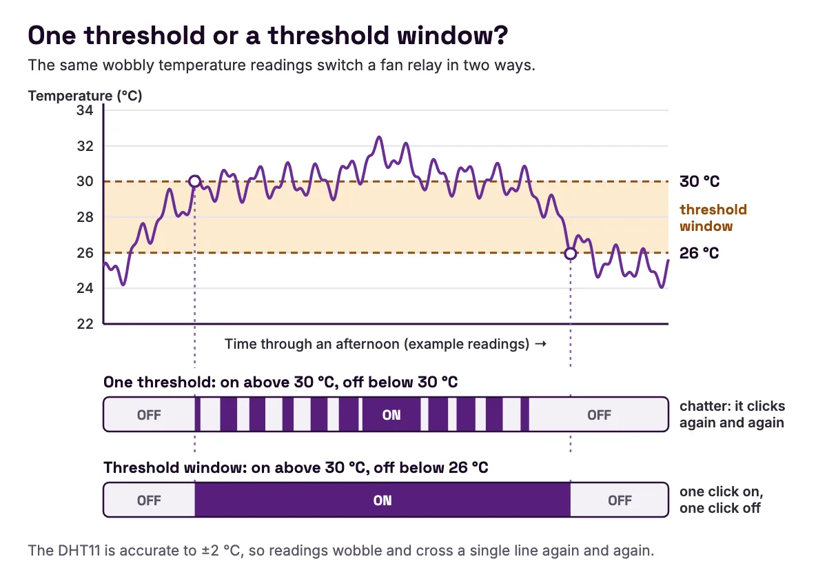
Now the fan runs above 30 °C and stops below 26 °C. The rules run on the board, not in your browser, so they keep working after you close the laptop. According to how rules run, the board reads its sensors once a second, and a condition must stay true for 0.3 seconds before a rule starts, so the fan reacts within about a second.
Why two thresholds instead of one
Why not "on above 30, off below 30"? Because readings wobble. Adafruit's DHT sensor guide (opens in a new tab) gives the DHT11 an accuracy of ±2 °C. A room sitting near 30 °C would cross a single line again and again, and the relay would click on and off. Lesson 27 calls this jitter. Engineers also call it chatter.
Chatter wears a relay out. Songle's datasheet (opens in a new tab) gives the contacts an electrical life of 100,000 operations, with a second, lower figure of 10,000 on the same line. It gives the moving parts alone a mechanical life of 10 million.
| Habit | Operations | Time to reach 100,000 |
|---|---|---|
| Chatter: one on-off cycle every 10 seconds | 360 an hour | 100,000 ÷ 360 = about 278 hours, under 12 days |
| Threshold window: 10 cycles a day | 10 a day | 100,000 ÷ 10 = 10,000 days, over 27 years |
- Habit
- Chatter: one on-off cycle every 10 seconds
- Operations
- 360 an hour
- Time to reach 100,000
- 100,000 ÷ 360 = about 278 hours, under 12 days
- Habit
- Threshold window: 10 cycles a day
- Operations
- 10 a day
- Time to reach 100,000
- 100,000 ÷ 10 = 10,000 days, over 27 years
Table note: worked from the higher electrical-life figure in the Songle datasheet (opens in a new tab). With its lower figure of 10,000, both times shrink tenfold. Read the rows as a comparison between two habits, not a forecast.
The 4-degree gap between 26 and 30 is a threshold window, and it keeps the relay quiet. Lesson 27 on range logic and threshold windows builds on it, and our coming guide to hysteresis and why a fan keeps switching on and off explains the idea in depth.
Two limits to know. The board has no clock, so a rule cannot say "fan on at 3 pm"; a Timer rule repeats at a set interval instead. And while a rule is using the relay, its dashboard switch is locked, so stop or delete the rule to take manual control back.
Common relay mistakes, with causes and fixes
The relay clicks, but the fan or bulb stays off
Cause: The load is wired to NC instead of NO, or the load circuit has no power. A relay is only a switch. It does not supply power by itself.
Fix: With the USB cable unplugged, wire the board's 5V to COM, NO to the load and the load's other lead to GND. Use the continuity check above if you are unsure which screw is which.
The dashboard switch moves, but there is no click
Cause: The module is not fully in the socket marked 23. Or you uploaded your own sketch, so the MakerBuddy firmware is no longer on the board to answer the dashboard.
Fix: Unplug the USB cable, push the module firmly into socket 23, plug the cable back in and connect again. If you replaced the firmware, put it back with Install by USB.
The relay clicks on and off by itself
Cause: One threshold, with a sensor reading that wobbles around it.
Fix: Use two rules with a gap, such as on above 30 °C and off below 26 °C.
Pressing Stop on the rule leaves the fan running
Cause: Stopping a rule never switches outputs off. It just stops the rule where it is.
Fix: After you stop the rule, switch the relay off on its card. To have the fan switch off by itself, use a second rule, like the Fan off rule above.
FAQ
What is the main function of a relay?
A relay lets a small electrical signal turn a separate, bigger circuit on or off. The signal powers a coil, and the coil's magnetism moves a switch. Because no wire joins the two circuits, the relay also keeps the controller apart from the load.
What is the difference between a switch and a relay?
An ordinary switch is moved by your hand. A relay is a switch moved by an electromagnet, so a sensor, a thermostat or a microcontroller can operate it from a distance.
Is a relay basically a fuse?
No. An ordinary fuse breaks a circuit once, when too much current flows, and then it must be replaced. A relay is a switch that a controller can open and close again and again. Many circuits use both: the relay switches the load, and a fuse protects the wiring.
Which relay is used in AC and DC?
An electromechanical relay can switch either, as long as the load stays within the contact ratings on its datasheet. Solid-state relays are built differently for AC and DC loads, because, as Texas Instruments explains (opens in a new tab), the thyristors used for AC cannot turn off a DC current. The MakerBuddy kit's relay only switches a small 5 V DC load.
What are the four types of relays?
There is no single official list of four. Panasonic's introduction to relays (opens in a new tab) splits control relays into two families, mechanical and semiconductor. Four kinds worth knowing as a student are the standard electromechanical relay, the latching relay, the solid-state relay and the relay module.
How many volts does a relay need to turn on?
It depends on the coil. Songle's SRD datasheet (opens in a new tab) lists coils from 5 V to 48 V, and its 5 V version pulls in by 3.75 V and is sure to let go below 0.5 V. On a relay module, the coil gets its full 5 V from the supply, and the control pin only switches the module's transistor.
How does a relay module work?
A relay module puts a relay on a small board with a transistor, a protection diode, an indicator LED and screw terminals. Your pin switches the transistor, and the transistor switches the coil. That is how a 3.3 V ESP32 pin drives a 5 V relay with just three wires: signal, ground and power.
Is it safe for students to use a relay?
Yes, when the load is low-voltage. In the MakerBuddy kit the relay switches a small 5 V fan or bulb powered from the board, wired with a teacher and the USB cable unplugged. Mains electricity is never part of a student activity. More guides like this one are on the MakerBuddy blog.
Sources
- Panasonic: Introduction to Relays, What Is a Relay? (opens in a new tab)
- Arduino Docs: Arduino 4 Relays Shield Basics (opens in a new tab)
- Arduino Docs: Transistor Motor Control (opens in a new tab)
- LCSC: Songle Relay SRD-05VDC-SL-C specifications (opens in a new tab)
- Songle: SRD series relay datasheet (Chinese, hosted by LCSC) (opens in a new tab)
- Espressif: ESP32 Series Datasheet, Table 5-3 DC characteristics (opens in a new tab)
- TE Connectivity: Relay Coil Suppression with DC Relays (opens in a new tab)
- Omron (on Digi-Key): Low Signal Relays training module, latching relays (opens in a new tab)
- Texas Instruments: A Modern Approach to Solid-state Relay Design (opens in a new tab)
- Adafruit: DHT11, DHT22 and AM2302 Sensors overview (opens in a new tab)