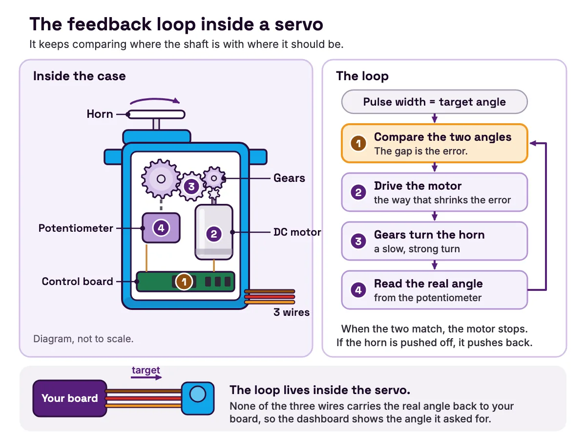
What is a servo motor? A servo motor is a motor that turns to the angle you ask for and then holds it there. Inside its small case are a DC motor, a row of gears, a sensor that measures the shaft's position and a tiny control board. The board keeps comparing where the shaft is with where it should be, and drives the motor until the two match. That constant checking is called a feedback loop. It is what makes a servo different from an ordinary motor, which just spins while it has power.
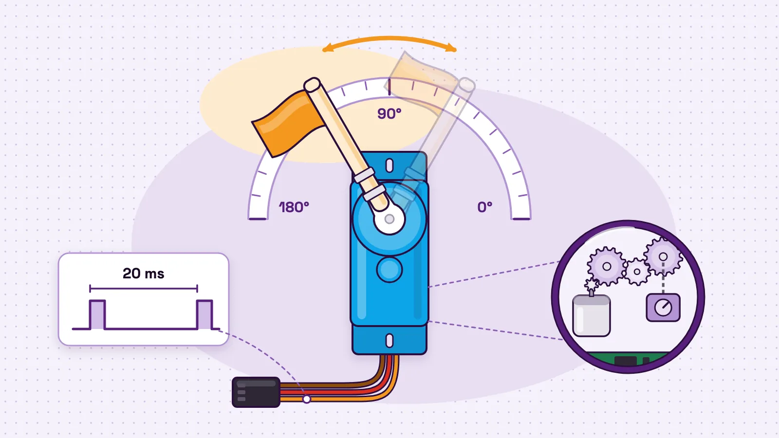
A hobby servo has three wires: power, ground and signal. The SG90 data sheet (opens in a new tab) draws the signal as a pulse every 20 ms, 50 times a second. The width of each pulse, about 1 to 2 ms, sets the angle.
Below, you will see how that works, then move the SG90 in the MakerBuddy kit with no code. This builds on our guide to actuators and output devices and follows Lesson 14: Introduction to Motors.
What is a servo motor? A simple definition
Servo is short for servomechanism. SparkFun's hobby servo tutorial (opens in a new tab) defines a servomechanism as a device that uses feedback to achieve the result you want. A servo motor uses feedback to control position.
Two families share the name. SparkFun's tutorial covers hobby, or radio-control, servos, made mainly to steer radio-controlled models and also useful in robots. The large servo motors in industrial machinery are different: as ADVANCED Motion Controls explains in its servo motor guide (opens in a new tab), they are often paired with an encoder or resolver to read their position, and take commands through a separate servo drive.
This guide is about hobby servos like the kit's SG90. Its data sheet (opens in a new tab) calls it a 9 g micro servo, about 22.2 × 11.8 × 31 mm, that turns roughly 180 degrees: 90 each way from the middle.
How does a servo motor work? Inside the feedback loop
What is inside the case
SparkFun took a servo apart in the Show Me The Guts part of its tutorial (opens in a new tab) and found four things.
- 1
A small DC motor.
It spins fast, in either direction.
- 2
Gears.
They slow the motor down and turn its fast spin into a slow, strong turn at the output shaft. Cheap servos have plastic gears, which strip more easily if the motor is jammed or overloaded.
- 3
A potentiometer.
It is fixed to the output shaft, so its reading changes as the shaft turns. This is the position sensor. The turning knob on the MakerBuddy board is the same kind of part, as our guide to how a potentiometer works explains.
- 4
A small circuit board.
A chip measures the incoming pulse, and transistors, which SparkFun thinks form an H-bridge, steer current through the motor one way or the other.
The feedback loop, step by step
- 1
Your board sends a pulse. The servo measures its width. That width is the target angle.
- 2
The potentiometer reports the angle the shaft is really at.
- 3
The circuit compares the two. The difference is the error.
- 4
It drives the motor in whichever direction makes the error smaller.
- 5
When the two match, the motor stops.
- 6
If something pushes the horn away, the error comes back, and the servo pushes back.
Engineers call this closed-loop control, because the result loops back into the decision. Lesson 14 shows it with a light cardboard pointer. Never twist the horn by hand, though: forcing it can damage the gears.
The loop lives inside the servo
None of the three wires carries the real angle back to your board. Your board sends a target and trusts the servo to reach it. That is why the MakerBuddy pin notes say the servo holds its last angle but cannot report where it really is. If the arm is jammed at 40°, the dashboard still shows the 90° it asked for.
Servo motor wires: what the three wires do
Arduino's servo motor basics (opens in a new tab) names the three wires power, ground and signal. Power is typically red, ground black or brown, and signal yellow or orange. Brands disagree on colours, but SparkFun's colour-coding table (opens in a new tab) shows the pins usually come in the same order: ground on pin 1, power on pin 2 in the middle, signal on pin 3.
| What the wire does | SG90 (the kit's servo) | JR scheme | Futaba scheme | Hitec scheme | MakerBuddy socket pin |
|---|---|---|---|---|---|
| Ground (−) | Brown | Brown | Black | Black | GND |
| Power (+) | Red | Red | Red | Red | VCC (middle) |
| Signal (the pulse) | Orange | Orange | White | Yellow | 19 |
- What the wire does
- Ground (−)
- SG90 (the kit's servo)
- Brown
- JR scheme
- Brown
- Futaba scheme
- Black
- Hitec scheme
- Black
- MakerBuddy socket pin
- GND
- What the wire does
- Power (+)
- SG90 (the kit's servo)
- Red
- JR scheme
- Red
- Futaba scheme
- Red
- Hitec scheme
- Red
- MakerBuddy socket pin
- VCC (middle)
- What the wire does
- Signal (the pulse)
- SG90 (the kit's servo)
- Orange
- JR scheme
- Orange
- Futaba scheme
- White
- Hitec scheme
- Yellow
- MakerBuddy socket pin
- 19
Table note: SG90 colours from the SG90 data sheet (opens in a new tab); brand schemes from SparkFun's tutorial (opens in a new tab), which also lists a Hitec variant with a brown power wire, so brown does not always mean ground. Socket labels as printed on the board.
SparkFun's rule of thumb: the drabbest colour, black or brown, is usually ground, and red is usually power. When in doubt, check the documentation, and don't plug it in backwards.
The red wire: power
The red wire feeds the motor. The SG90 data sheet (opens in a new tab) gives an operating voltage of 4.8 V, about 5 V, and SparkFun (opens in a new tab) puts the absolute maximum at 5.5 V when a microcontroller is in charge. The current depends on the load. Arduino's servo guide (opens in a new tab) says a Feetech 9 g mini servo needs only 5 to 6 mA standing still, but up to 800 mA when loaded or blocked.
The brown wire: ground
Ground is the return path for the motor current and the level the signal is measured against, so the servo and the board must share it. When servos run from their own supply, SparkFun (opens in a new tab) recommends a common ground between that supply and the processor's.
The orange wire: signal
The orange wire carries information, not power. It is the pulse that says which angle to go to, so your board's signal pin only has to switch on and off at the right moments.
The three wires on MakerBuddy
On the MakerBuddy board you never handle bare wires. The servo plugs into the three-pin socket marked 19 on the bottom edge. Its pins are printed 19, VCC and GND: signal, power in the middle, then ground. The plug fits only one way, so never force it, and attach or remove the servo only with the USB cable unplugged.
How the pulse width sets the angle
The signal is a kind of PWM, or pulse width modulation. SparkFun's tutorial (opens in a new tab) describes a pulse every 20 ms (50 Hz) that is 1 to 2 ms wide, with 1.5 ms putting the servo in the centre of its range. A shorter pulse turns it one way, a longer pulse the other. Our coming guide to PWM with an LED explains PWM itself.
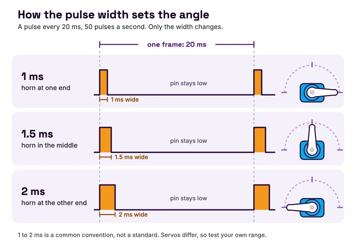
Three things about this signal surprise most students.
- The width is the message. The servo times how long each pulse stays on and turns that time into an angle.
- The pulse has to keep coming. A servo holds its angle because the board keeps sending the same pulse. The MakerBuddy firmware keeps it running at the last angle, even while a rule waits between steps.
- Tiny changes are ignored. The SG90 data sheet (opens in a new tab) lists a dead band width of 10 µs: the servo does not react to a change smaller than that.
Why 1 to 2 ms is not the whole story
SparkFun calls 1 to 2 ms more of a convention than a standard. Some servos accept shorter or longer pulses and swing further, but not all, and driving a servo past its limits can strip its gears. So different tools use different numbers.
| Who | Shortest pulse | Longest pulse | Travel over that range |
|---|---|---|---|
| SparkFun, common hobby servos | 1 ms | 2 ms | About 90° |
| SG90 data sheet | About 1 ms | About 2 ms | About 180° |
| Arduino Servo library defaults | 544 µs | 2,400 µs | write(0) to write(180) |
| MakerBuddy firmware | 500 µs | 2,500 µs | 0° to 180° |
- Who
- SparkFun, common hobby servos
- Shortest pulse
- 1 ms
- Longest pulse
- 2 ms
- Travel over that range
- About 90°
- Who
- SG90 data sheet
- Shortest pulse
- About 1 ms
- Longest pulse
- About 2 ms
- Travel over that range
- About 180°
- Who
- Arduino Servo library defaults
- Shortest pulse
- 544 µs
- Longest pulse
- 2,400 µs
- Travel over that range
- write(0) to write(180)
- Who
- MakerBuddy firmware
- Shortest pulse
- 500 µs
- Longest pulse
- 2,500 µs
- Travel over that range
- 0° to 180°
Table note: from SparkFun's tutorial (opens in a new tab), the SG90 data sheet (opens in a new tab) and the Arduino Servo library's Servo.h (opens in a new tab); the MakerBuddy figures come from the firmware excerpt below.
So a command of 0° or 180° is a request, not a promise. Your servo may hit its stop early or stop short. Lesson 14 has you find your own servo's useful angles and stay a little inside them.
Worked example: the numbers behind one SG90 move
From an angle to a pulse
This is the function the MakerBuddy firmware uses to turn an angle into a pulse on socket 19. It comes from the board's public source, linked from the Arduino development notes. There, SERVO_US_MIN is 500 and SERVO_US_MAX is 2500.
// From the MakerBuddy firmware: the servo runs on LEDC channel 8, 50 Hz, 16-bit.
void writeServo(int angle) {
  angle = constrain(angle, 0, 180);
  uint32_t us = (uint32_t)map(angle, 0, 180, SERVO_US_MIN, SERVO_US_MAX);
  uint32_t duty = (uint32_t)((uint64_t)us * 65535UL / 20000UL);
  ledcWrite(SERVO_PIN, duty);
}
Follow it through for 90°.
- 1
constrainkeeps the angle between 0 and 180, so a bad number can never push the servo past its range. - 2
mapspreads 0–180° evenly over 500–2,500 µs: 2,000 µs across 180 degrees, about 11.1 µs per degree. So 90° becomes 1,500 µs. - 3
At 50 Hz one frame lasts 20,000 µs, and 16-bit resolution splits it into 65,535 steps.
- 4
The duty value is 1,500 × 65,535 ÷ 20,000 = 4,915 (rounded down). The pin stays on for 1.5 ms of every 20 ms.
| Angle | Pulse width | Duty value (out of 65,535) |
|---|---|---|
| 0° | 500 µs | 1,638 |
| 45° | 1,000 µs | 3,276 |
| 90° | 1,500 µs | 4,915 |
| 135° | 2,000 µs | 6,553 |
| 180° | 2,500 µs | 8,191 |
- Angle
- 0°
- Pulse width
- 500 µs
- Duty value (out of 65,535)
- 1,638
- Angle
- 45°
- Pulse width
- 1,000 µs
- Duty value (out of 65,535)
- 3,276
- Angle
- 90°
- Pulse width
- 1,500 µs
- Duty value (out of 65,535)
- 4,915
- Angle
- 135°
- Pulse width
- 2,000 µs
- Duty value (out of 65,535)
- 6,553
- Angle
- 180°
- Pulse width
- 2,500 µs
- Duty value (out of 65,535)
- 8,191
Two results stand out. One duty step is about 0.3 µs, far finer than the servo can follow. And one degree is about 11 µs, just over the 10 µs dead band in the SG90 data sheet (opens in a new tab). So a 1° move is close to the smallest change the SG90 promises to notice.
How long a move takes
The SG90 data sheet (opens in a new tab) gives an operating speed of 0.1 s per 60°, so a full 180° swing takes at least 0.3 s. Treat that as the best case. Ask for 120° in 100 ms and the servo simply arrives late, so give every move in a rule at least that long.
How much it can hold
Torque is turning force. The SG90 data sheet (opens in a new tab) gives a stall torque of 1.8 kgf·cm: the servo can just hold 1.8 kg pulling 1 cm from the centre of the shaft. Torque is force times distance, so the further out the load, the less it can hold.
| Arm length (load at the tip) | Most it can hold before it stalls |
|---|---|
| 1 cm | 1.8 kg |
| 2 cm | 0.9 kg |
| 5 cm | 360 g |
| 10 cm | 180 g |
- Arm length (load at the tip)
- 1 cm
- Most it can hold before it stalls
- 1.8 kg
- Arm length (load at the tip)
- 2 cm
- Most it can hold before it stalls
- 0.9 kg
- Arm length (load at the tip)
- 5 cm
- Most it can hold before it stalls
- 360 g
- Arm length (load at the tip)
- 10 cm
- Most it can hold before it stalls
- 180 g
Table note: each row is the data sheet's 1.8 kgf·cm divided by the arm length.
Stall is where the servo can no longer move. It is a limit, not a working load. A stalled servo buzzes, draws extra current and can damage its gears, which is why Lesson 14 keeps arms short and light.
Servo vs DC motor vs stepper motor
A servo is one of three motor families in student projects. Each solves a different problem.
| Motor | How it moves | Knows its position? | How you control it | Good for |
|---|---|---|---|---|
| Positional servo (the SG90) | Turns to an angle in a limited range | Yes, with its own potentiometer | Pulse width | Gates, lids, pointers, flaps |
| Continuous-rotation servo | Spins either way; the pulse sets speed and direction | No | Pulse width; 1.5 ms usually means stop | Small, slow wheels |
| DC motor | Spins nonstop while powered | No | On and off, or speed through a transistor or driver | Fans and wheels |
| Stepper motor | Moves in small, exact steps | It counts steps instead | Coil pulses through a driver | Precise positioning |
- Motor
- Positional servo (the SG90)
- How it moves
- Turns to an angle in a limited range
- Knows its position?
- Yes, with its own potentiometer
- How you control it
- Pulse width
- Good for
- Gates, lids, pointers, flaps
- Motor
- Continuous-rotation servo
- How it moves
- Spins either way; the pulse sets speed and direction
- Knows its position?
- No
- How you control it
- Pulse width; 1.5 ms usually means stop
- Good for
- Small, slow wheels
- Motor
- DC motor
- How it moves
- Spins nonstop while powered
- Knows its position?
- No
- How you control it
- On and off, or speed through a transistor or driver
- Good for
- Fans and wheels
- Motor
- Stepper motor
- How it moves
- Moves in small, exact steps
- Knows its position?
- It counts steps instead
- How you control it
- Coil pulses through a driver
- Good for
- Precise positioning
Table note: continuous-servo facts from SparkFun's tutorial (opens in a new tab), which gives around 60 RPM as a common top speed; stepper facts from Arduino's stepper motor guide (opens in a new tab), which says steppers reach high accuracy without any feedback; DC motor facts from Lesson 14.
A continuous-rotation servo looks just like a normal one, so SparkFun says to look for a "360°" mark on the packaging. Our coming guides to 360-degree servos vs standard servos and servo vs stepper vs DC motor go deeper.
Pick a servo when a part must go to a position and stay there: a barrier, a bin lid, a dial pointer or a flag.
How the MakerBuddy kit drives its SG90
The SG90 is one of the nine plug-in parts in every MakerBuddy kit, listed with the rest of what comes in a MakerBuddy kit. The firmware gives it its own PWM channel on a second timer, so, as the technical details explain, changing the colour light never disturbs the servo.
Four ways to move it
| Way | Where you set it | What it does |
|---|---|---|
| Slider | Servo Motor card, Position (0° - 180°) | Goes straight to the angle; click it and use the arrow keys for 1° steps |
| Knob | Potentiometer Mapping card, set to Servo | Turning the knob sweeps 0° to 180°; goes back to None after every restart |
| A sensor | Servo Mapping card | One sensor drives the angle across 0–180°, with Invert direction |
| A rule | A Servo Move step | Goes to an angle, moves by an amount, or sweeps, over a time you set |
- Way
- Slider
- Where you set it
- Servo Motor card, Position (0° - 180°)
- What it does
- Goes straight to the angle; click it and use the arrow keys for 1° steps
- Way
- Knob
- Where you set it
- Potentiometer Mapping card, set to Servo
- What it does
- Turning the knob sweeps 0° to 180°; goes back to None after every restart
- Way
- A sensor
- Where you set it
- Servo Mapping card
- What it does
- One sensor drives the angle across 0–180°, with Invert direction
- Way
- A rule
- Where you set it
- A Servo Move step
- What it does
- Goes to an angle, moves by an amount, or sweeps, over a time you set
Lesson 14 uses the slider, Lesson 9 the knob, and Lesson 21 introduces rules.
Only one of the four controls the servo at a time. While a rule, the knob or a sensor holds it, the board refuses slider commands and the card shows it is locked. The servo control notes list every case. To get the slider back, stop the rule, or set the knob and the sensor to None.
Sensor following: the maths
The Servo Mapping card spreads each sensor's full range across 0–180°: 0–100 for light, soil, gas and humidity, 0–50 °C for the DHT11 and −55 to 125 °C for the DS18B20, as the knob and motor settings explain. The board ignores changes under 3° and glides to each new angle in half a second.
| Sensor | Range on the card | Turn per unit | Change needed to move 3° |
|---|---|---|---|
| Light, soil, gas or humidity | 0–100 | 1.8° per point | About 1.7 points |
| DHT11 temperature | 0–50 °C | 3.6° per °C | About 0.8 °C |
| DS18B20 temperature | −55 to 125 °C | 1° per °C | 3 °C |
- Sensor
- Light, soil, gas or humidity
- Range on the card
- 0–100
- Turn per unit
- 1.8° per point
- Change needed to move 3°
- About 1.7 points
- Sensor
- DHT11 temperature
- Range on the card
- 0–50 °C
- Turn per unit
- 3.6° per °C
- Change needed to move 3°
- About 0.8 °C
- Sensor
- DS18B20 temperature
- Range on the card
- −55 to 125 °C
- Turn per unit
- 1° per °C
- Change needed to move 3°
- 3 °C
So for a dial, the DS18B20 is the more accurate thermometer, ±0.5 °C from −10 to 85 °C per Adafruit's DS18B20 page (opens in a new tab), but its pointer waits for a 3 °C change. The DHT11 is rougher, ±2 °C per Adafruit's DHT guide (opens in a new tab), yet swings 3.6° per degree.
For a big, clear move over a small range, use a rule instead. A Condition rule can send the servo to a chosen angle when a reading crosses a line, as our guide to if-then statements with real sensors shows.
Worked example: a flag-waving rule with no code
This rule waves a small flag for as long as it runs, using only the dashboard.
- 1
Calibrate first.
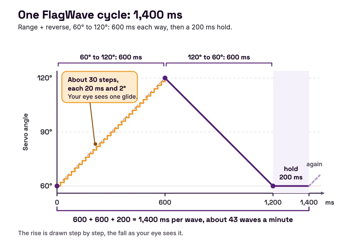
Fit a light craft-stick flagpole to the horn. With the slider, find a low and a high angle where the flag never hits anything, and test each three times, as Lesson 14 does. This example uses 60° and 120°.
- 2
Check the speed.
A 60° move needs at least 0.1 s on the SG90. Giving it 600 ms makes the wave slow and smooth.
- 3
Create the rule.
Choose Create Rule, type the Rule Name FlagWave and pick the Loop Mode Forever.
- 4
Add one step.
Action: Servo Move. Movement type: Range + reverse. Start angle (°): 60. Destination angle (°): 120. Duration per direction (ms): 600. Hold after movement (ms): 200.
- 5
Save and watch.
The servo goes to 60°, glides to 120°, glides back, rests, and starts again.
- 6
Stop it.
Press Stop on the rule. The flag holds where it is, and the slider works again.
One cycle is two movements plus the hold: 600 + 600 + 200 = 1,400 ms, about 43 waves a minute. And while a rule moves the servo, the board updates the angle about every 20 ms, according to the timing table in the technical details. Over 600 ms that is about 30 small moves of 2° each, which your eye sees as one smooth glide.
Next, try the parking barrier in Lesson 29 and Lesson 30, where two Condition rules open and close a gate. Our coming smart parking system project walks through it, and the project ideas library has more servo builds.
Common servo problems: symptom, cause and fix
The servo buzzes and will not settle
Cause: It is pushing against its end stop or an obstacle. SparkFun (opens in a new tab) says servos driven past their end stops may hum or grind, and clicking means the gears are binding.
Fix: Move it back to a safe angle and keep inside the range you calibrated. If it buzzes nonstop or gets warm, power down and remove the obstruction, as Lesson 14 advises.
The arm jitters, or the board restarts when it moves
Cause: Not enough power. SparkFun (opens in a new tab) calls the rocking "hunting" and notes a straining servo can make the supply sag and reset a microcontroller. A loaded or blocked mini servo can draw up to 800 mA, according to Arduino's servo guide (opens in a new tab).
Fix: Use a good 5 V USB charger and cable, a lighter arm and no obstacles. For your own circuits, our coming guide to servo wiring, code and fixing jitter covers capacitors and separate supplies.
The arm hits the frame at 0° or 180°
Cause: Every SG90 is a little different, and the firmware's 500 to 2,500 µs range is wider than the 1 to 2 ms in the SG90 data sheet (opens in a new tab). The board also starts at 0° every time it powers up.
Fix: Refit the horn so 0° is a safe resting position, then use the angles you recorded, not the ends of the slider.
The horn turns freely, or the gears click
Cause: Stripped gears. SparkFun (opens in a new tab) says plastic gears are more likely to strip when the motor is jammed or overloaded.
Fix: Replace the servo. Next time, never twist the horn by hand, and stop the servo as soon as it strains.
FAQ
What is a servo motor in simple words?
A servo motor goes to the angle you tell it and stays there. Its own sensor and control board check its position and correct it. An ordinary motor just spins.
What is the main difference between a servo motor and a normal motor?
Feedback. A normal DC motor spins nonstop and does not know where its shaft is. A servo measures its shaft angle with a built-in potentiometer and drives the motor until it reaches the angle the pulse asks for. The trade-off is range: a standard hobby servo like the SG90 swings about 180°.
What are the three pins of a servo motor?
Ground, power and signal, usually in that order with power in the middle. On the SG90 they are brown, red and orange, as its data sheet (opens in a new tab) shows. Other brands use black for ground and white or yellow for signal, so check the documentation first.
Why are they called servo motors?
Servo is short for servomechanism, which SparkFun (opens in a new tab) describes as a device that uses feedback to achieve the result you want. The Wikipedia article on the servomechanism (opens in a new tab) traces the prefix to the Latin servus, meaning slave, and says the French term is believed to date from 1868, for engines that steered ships.
Can you run a servo motor continuously?
A standard servo cannot spin round and round, because its gears have a stop. Continuous-rotation servos do exist: SparkFun (opens in a new tab) explains that they turn the pulse into speed and direction, with 1.5 ms usually meaning stop. On MakerBuddy, a Forever rule keeps the SG90 moving back and forth, but always between 0° and 180°.
What are the disadvantages of a servo motor?
Hobby servos have a limited swing, modest strength and plastic gears that can strip. They draw a lot of current when stalled, and they cannot tell your board where they really are. Industrial servo systems are precise, but ADVANCED Motion Controls (opens in a new tab) notes they cost more up front and can be complex to set up and tune.
How do you check if a servo motor is working?
Move it to 0°, 90° and 180° and check that it stops cleanly at each. Send the same angle several times and check that the horn returns to the same spot. Warning signs are nonstop buzzing, jitter, clicking, a horn that turns freely by hand, or a warm case.
Can an ESP32 or Arduino power a servo directly?
Never power a servo from a signal pin. The pin only sends the pulse; the motor's power comes through the red wire. Arduino's servo guide (opens in a new tab) recommends an external supply because a loaded mini servo can draw up to 800 mA. On MakerBuddy, socket 19 carries the signal, power and ground for the kit's one SG90, so there is nothing to wire.
Do I need to write code to use a servo on MakerBuddy?
No. The lessons use the slider, the knob and rules. Your own Arduino sketch would replace the MakerBuddy firmware until you put it back with Install by USB. See our coming SG90 micro servo guide and the MakerBuddy blog for more.
Sources
- SG90 9 g Micro Servo data sheet (course copy, University of Hamburg) (opens in a new tab)
- SparkFun Learn: Hobby Servo Tutorial (opens in a new tab)
- Arduino Docs: Servo Motor Basics with Arduino (opens in a new tab)
- Arduino Servo library: Servo.h on GitHub (opens in a new tab)
- Arduino Docs: Arduino and Stepper Motor Configurations (opens in a new tab)
- ADVANCED Motion Controls: What is a Servo Motor (opens in a new tab)
- Wikipedia: Servomechanism (opens in a new tab)
- Adafruit Learning System: DHT11, DHT22 and AM2302 Sensors, Overview (opens in a new tab)
- Adafruit: Waterproof 1-Wire DS18B20 Digital temperature sensor (opens in a new tab)